Structure of golf iron head

A golf club head and structure technology, applied to golf balls, golf clubs, rackets, etc., can solve the problems of reducing elastic deformation capacity, vibration, affecting the structural strength of the club head 1, etc.

Inactive Publication Date: 2009-12-09
FUSHENG IND CO LTD
View PDF2 Cites 4 Cited by
  • Summary
  • Abstract
  • Description
  • Claims
  • Application Information

AI Technical Summary

Problems solved by technology

If the bonding edge 111 bears the concentrated stress for a long time, cracks may occur in the bonding edge 111, which will affect the structural strength of the club head 1
Although the above-mentioned conventional club head 1 is provided with the shock-absorbing sheet 14, the bonding method of the shock-absorbing sheet 14 inevitably forms a gap 142 between the shock-absorbing sheet 14 and the body 10.
As a result, in actual use, the shock-absorbing sheet 14 cannot absorb the concentrated stress of the bonding edge 111 due to the barrier of the gap 142, and the shock-absorbing sheet 14 also greatly reduces the ability to absorb the shock of the striking panel

Method used


Image

  • Structure of golf iron head
  • Structure of golf iron head
  • Structure of golf iron head

Examples


Example Embodiment

[0035] In order to make the above and other objectives, features and advantages of the present invention more obvious and understandable, the following is a detailed description of the preferred embodiments of the present invention in conjunction with the accompanying drawings:

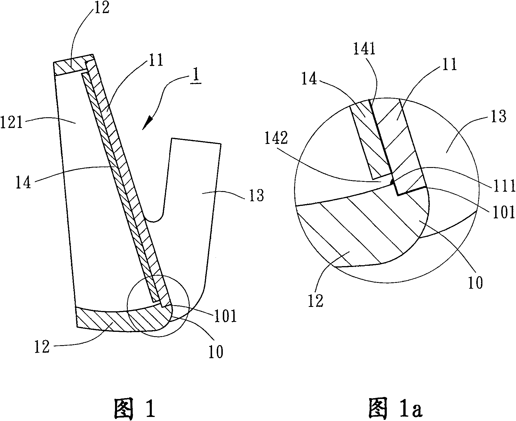
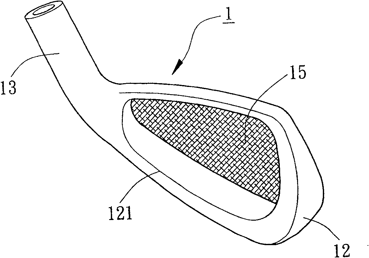
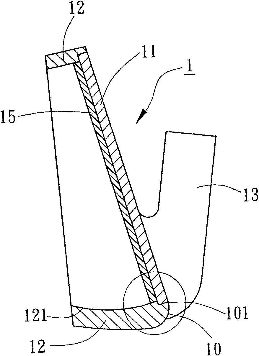
[0036] Please refer to figure 2 , 3 As shown in and 3a, the golf club head structure of the first embodiment of the present invention is a club head 1 made of metal and alloy materials. The club head 1 includes a body 10, a striking panel 11, a ring wall 12, and a set of Neck 13 and a strengthening plate 15. The front surface of the main body 10 can be formed with a panel joint 101 to combine with the striking panel 11. The striking panel 11 can optionally be joined to the panel of the main body 10 by embedding, pressing, brazing, welding, screwing, etc. The part 101 can also be directly formed on the main body 10 by means of integral molding. The striking panel 11 can be used to strike a golf ball. The ...


PUM


Abstract

A structure of golf club head is composed of a main body with a front surface and a surrounding wall, a shooting plate attached to said front surface of main body, and a strengthening plate attached to the back of said shooting plate. Its advantages are high structural strength and high effect to absorb the shooting vibration.

Description

Technical field [0001] The present invention relates to a golf club head structure, in particular to a golf club head structure in which a strengthening plate is arranged on the back of a striking panel to increase the structural strength. Background technique [0002] Traditional golf club head structure, such as figure 1 , 1a As shown, it is made of a metal material with a club head 1. The club head 1 includes a body 10, a striking panel 11, a ring wall 12, a neck 13 and a shock-absorbing sheet 14. The striking panel 11 is arranged on the The front of the main body 10 is used to hit golf balls. The ring wall 12 extends rearward from the periphery of the main body 10, and the ring wall 12 surrounds an opening 121 at the back. The collar 13 is used to combine a club (not shown). The shock-absorbing sheet 14 is made of rubber or carbon fiber material, and can be glued and bonded to the back of the striking panel 11 with an adhesive layer 141 to absorb the shock generated by the b...

Claims


Application Information

Patent Timeline
IPC IPC(8): A63B53/04A63B102/32
Inventor 陈建同
Owner FUSHENG IND CO LTD
Why Eureka
Try Eureka