
Micro-pressure stress test seat

A technology of compressive stress and test socket, which is applied in the direction of the measuring device casing, etc., can solve the problems of package damage, inability to quickly adjust the contact stress, and large elastic force of the second elastic element, etc.

Active Publication Date: 2013-07-10
KING YUAN ELECTRONICS
View PDF10 Cites 0 Cited by
  • Summary
  • Abstract
  • Description
  • Claims
  • Application Information

AI Technical Summary

Problems solved by technology

[0003] Known test sockets mostly use the method of pressing the package from top to bottom, and the pressing element is controlled by the elasticity of the second elastic element. When the package is to be placed, the second elastic element is pressed to make the pressing element Open, when the package is placed and positioned, release the second elastic element to make the pressing element elastically rebound to press the package, but this method often provides a relatively large moment due to the excessive elasticity of the second elastic element , so that the pressing element produces a large impact force on the package. As the package becomes more and more sophisticated, this impact will often cause damage to the package
[0004] On the other hand, depending on the application and precision of the package, it is necessary to use different contact stresses for testing. However, most of the known test sockets provide fixed contact stress. If different contact stress is required, it is necessary to manufacture Different test sockets, but cannot quickly adjust the required contact stress

Method used


Image

  • Micro-pressure stress test seat
  • Micro-pressure stress test seat
  • Micro-pressure stress test seat

Examples


Embodiment Construction

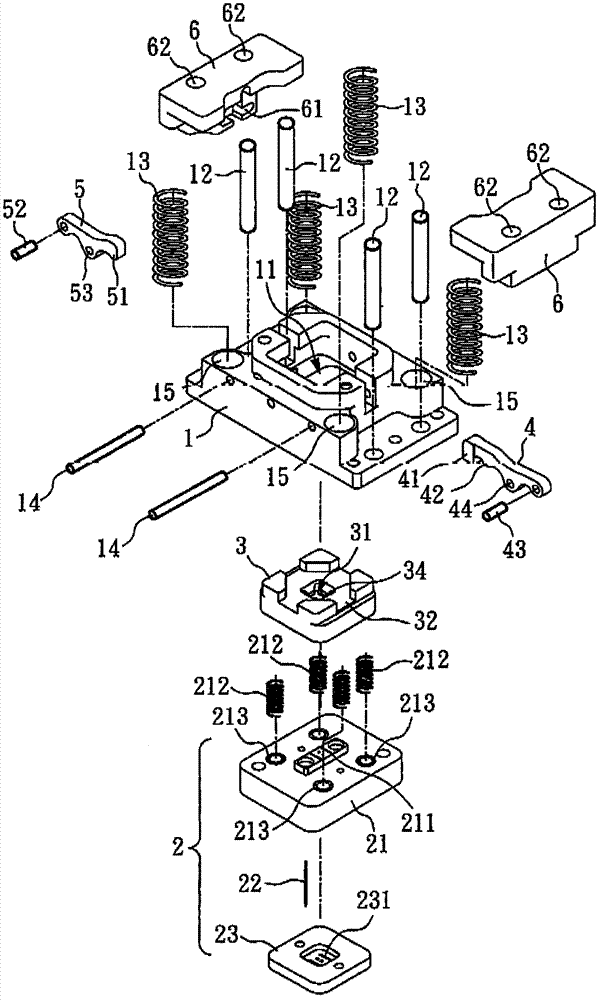
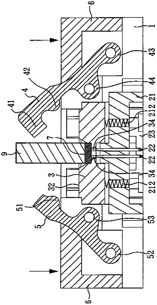
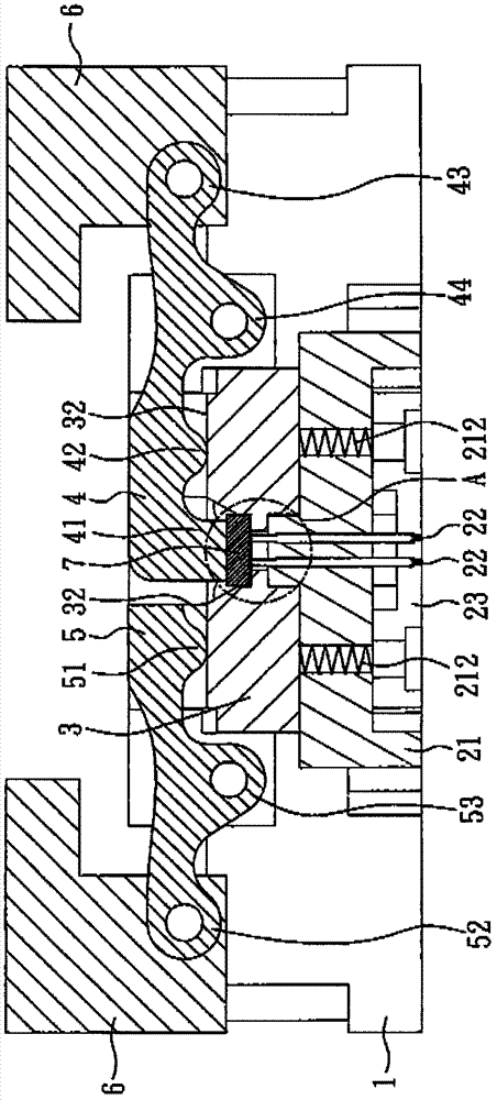
[0021] see figure 1 , figure 1 It is an exploded view of a preferred embodiment of the present invention. The micro-compressive stress test seat of this embodiment includes: a base 1 , a test port 2 , a guide seat 3 , a long press 4 , a short press 5 , and two press pieces 6 . The base 1 is provided with an accommodating groove 11, the test port 2 is arranged in the accommodating groove 11 of the base 1, the guide seat 3 is placed in the accommodating groove 11 of the base 1, and is located above the test port 2, A plurality of first elastic elements 212 are interposed between the guide seat 3 and the test port 2 , and in this embodiment, the plurality of first elastic elements 212 are springs.

[0022] The test port 2 includes a bottom plate 23 , a terminal fixing seat 21 , and a plurality of contact terminals 22 . Wherein, the terminal fixing seat 21 may include a plurality of grooves 213 to accommodate a plurality of first elastic elements 212 interposed between the guid...


PUM


Abstract

The invention relates to a micro-pressure stress test seat which comprises a base seat, a test port, a guiding seat, a pair of long pressure pliers, a pair of short pressure pliers and two pressing components, wherein the pair of the long pressure pliers and the pair of the short pressure pliers are arranged on two corresponding sides of the base seat, the two pressing components respectively cover the pair of the long pressure pliers and the pair of the short pressure pliers. A convex surface is arranged on the pair of the long pressure pliers and a check and combination surface is arranged on the pair of the short pressure pliers, and the convex surface and the check and combination surface can be abutted against the guiding seat in an optional mode. When the two pressing components on two sides are pressed down, a chip to be tested can be placed, then the pressing components is let go, the pair of the long pressure pliers and the pair of the short pressure pliers first return to press the guiding seat, a square pressure head is then pressed to fit with the chip to be tested, so that most impact force is absorbed by the guiding seat and damage of the chip to be tested is avoided.

Description

technical field [0001] The invention relates to a micro-compressive stress test seat, in particular to a test seat suitable for testing electronic packaging components. Background technique [0002] Various electronic component chips, such as integrated circuits (Integrated Circuit, IC), micro electromechanical systems (Micro Electro Mechanical Systems, MEMS), etc., are packaged into packages after the chip packaging process, and then the packages need to be placed in the testing machine. The electrical test is carried out in the test socket to check whether the function of the package is normal and whether the characteristics meet the customer's requirements. Before entering the test machine for testing, the package needs to be placed in the test socket for subsequent testing. [0003] Known test sockets mostly use the method of pressing the package from top to bottom, and the pressing element is controlled by the elasticity of the second elastic element. When the package ...

Claims


Application Information

Patent Timeline
IPC IPC(8): G01R1/04
Inventor 刘光祥林威成
Owner KING YUAN ELECTRONICS
Learn More