Check patentability & draft patents in minutes with Patsnap Eureka AI!

Electrowetting display device

A technology for display devices, voltages, used in static indicators, instruments, optics, etc., to solve problems such as unacceptable, poor grayscale stability or reproducibility

Inactive Publication Date: 2009-12-09
LIQUAVISTA BV
View PDF4 Cites 5 Cited by
  • Summary
  • Abstract
  • Description
  • Claims
  • Application Information

AI Technical Summary

Problems solved by technology

However, in practice the resulting grayscale stability or reproducibility was experimentally found to be very poor and unacceptable for most applications

Method used


Image

  • Electrowetting display device
  • Electrowetting display device
  • Electrowetting display device

Examples


Embodiment Construction

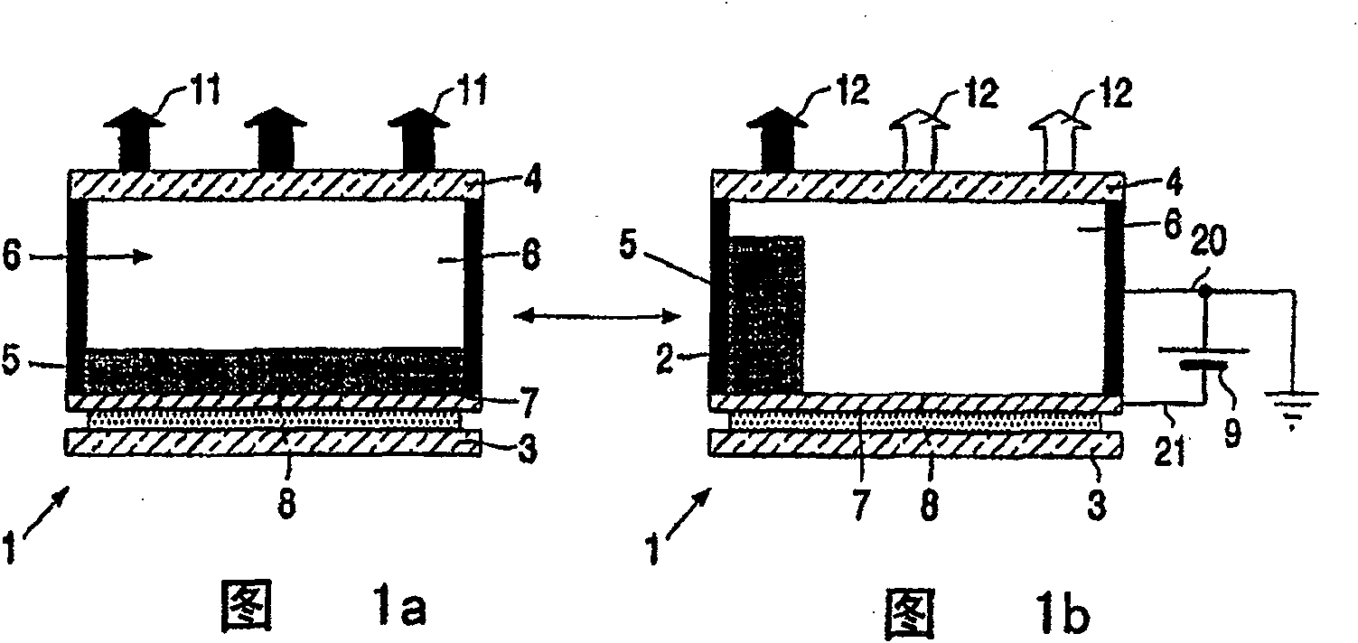
[0022] Fig. 1 shows a cross-sectional view of a part of a display device 1 illustrating the principle on which the display device according to the invention is based. A first liquid 5 and a second liquid 6 , which are mutually immiscible, are arranged between the two transparent substrates or carrier plates 3 , 4 . The first liquid 5 is for example an alkane like hexadecane or a (silicone) oil as in this example. The second liquid 6 is conductive or polar, such as water or a salt solution (eg KCl solution mixed with water and ethanol).

[0023] In the first state, when no external voltage is applied ( Figure 1a ), the liquids 5, 6 are adjacent to first and second transparent support plates 3, 4 made of eg glass or plastic. On the first support plate 3 there is arranged a transparent electrode 7 such as indium oxide (tin) and an intermediate non-wettable (hydrophobic) layer 8, in this case an amorphous fluoropolymer (AF1600).

[0024] When (the voltage source 9) applies a v...


PUM


Abstract

Several possibilities are presented for driving means (13, 14, 15) for optical switches, in particular for displays (1) based on the principle of electrowetting. The principle uses an optical switch comprising a first liquid (5) and a second liquid (6) immiscible with each other in the space between a first transparent support plate (3) and a second support plate (4) , the second liquid is conductive or polar.

Description

technical field [0001] The invention relates to a display device comprising a picture element (pixel) having on a first transparent support plate at least one first liquid immiscible with each other and a second liquid which is electrically conductive or polarized. Background technique [0002] Usually the liquid is contained in the space between the first transparent support plate and the second support plate, but this is not absolutely necessary. [0003] If the liquid is (coloured) oil and the second liquid is water, this provides (due to interfacial tension) a two-layer system comprising a water layer and an oil layer. However, if a voltage is applied between the water and the electrodes on the first support plate, the oil layer moves aside or ruptures due to electrostatic forces. As some of the water now seeps into the oil layer, the graphic elements become partially transparent. [0004] A display device based on this principle is described in PCT application WO 03 / ...

Claims


Application Information

Patent Timeline
Patent Type & Authority Patents(China)
IPC IPC(8): G09G3/34G02B26/02G09G3/20
CPCG02B26/005G09G3/3433G09G3/2011G09G2310/06G09G3/348G09G2300/08G09G2310/0254G09G3/38G02F1/163G09G3/34
Inventor G·周L·M·哈格R·H·M·科蒂M·T·约翰逊B·J·菲恩斯特拉R·A·海斯A·R·弗兰克林
Owner LIQUAVISTA BV
Features
  • R&D
  • Intellectual Property
  • Life Sciences
  • Materials
  • Tech Scout
  • Unparalleled Data Quality
  • Higher Quality Content
  • 60% Fewer Hallucinations
Learn More