Inclining and rotating table apparatus

A technology of rotary table and clamping device, which is applied in the direction of feeding device, manufacturing tools, metal processing equipment, etc.

Active Publication Date: 2009-12-30
SANKYO SEISAKUSHO +1
View PDF10 Cites 0 Cited by
  • Summary
  • Abstract
  • Description
  • Claims
  • Application Information

AI Technical Summary

Problems solved by technology

In these cases there is a difference between the relative positions of the shaft and the clamping device

Method used


Image

  • Inclining and rotating table apparatus
  • Inclining and rotating table apparatus
  • Inclining and rotating table apparatus

Examples


Embodiment Construction

[0040] At least the following aspects will be clearly understood by referring to the technical features of the present invention in conjunction with the accompanying drawings.

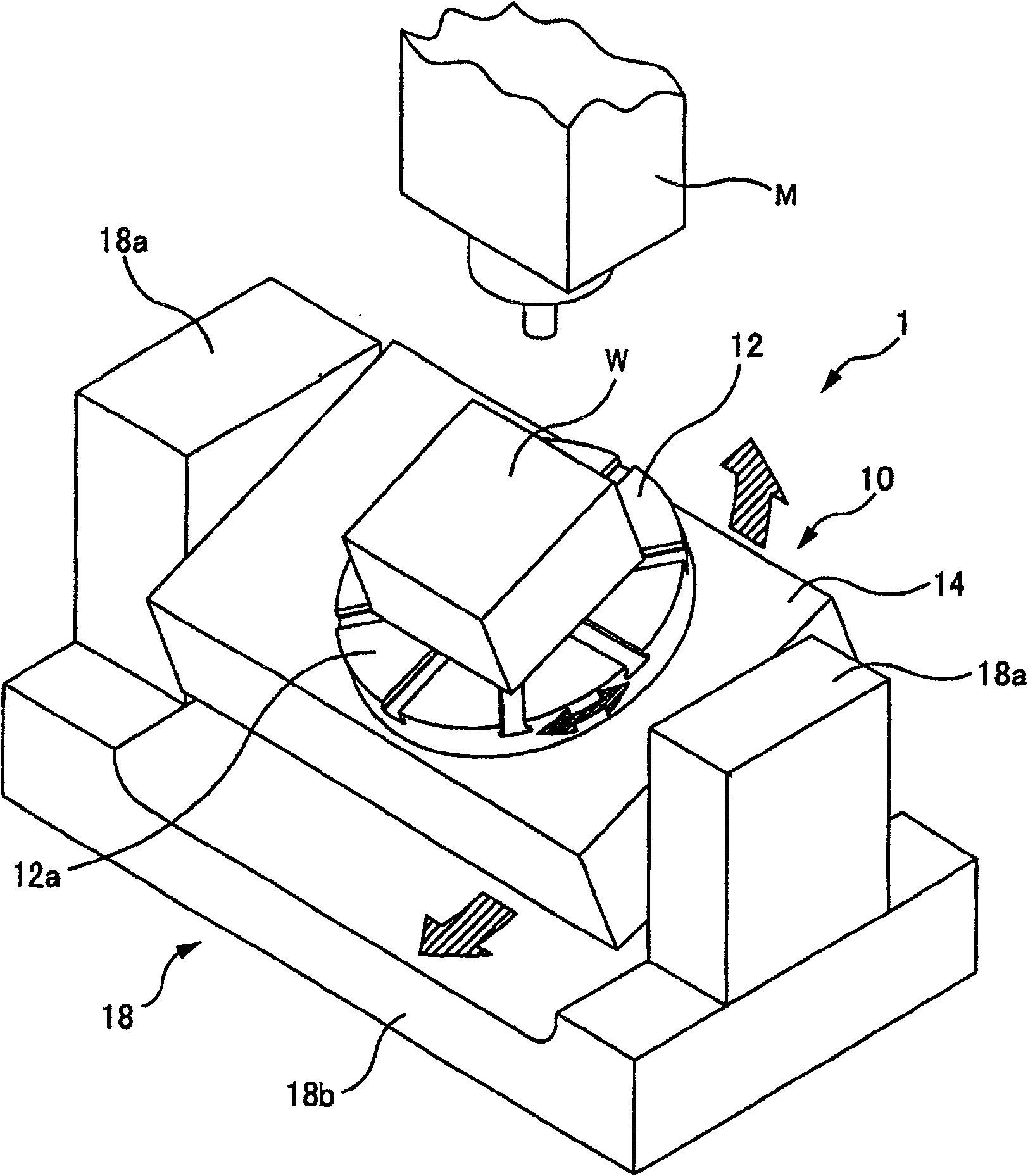
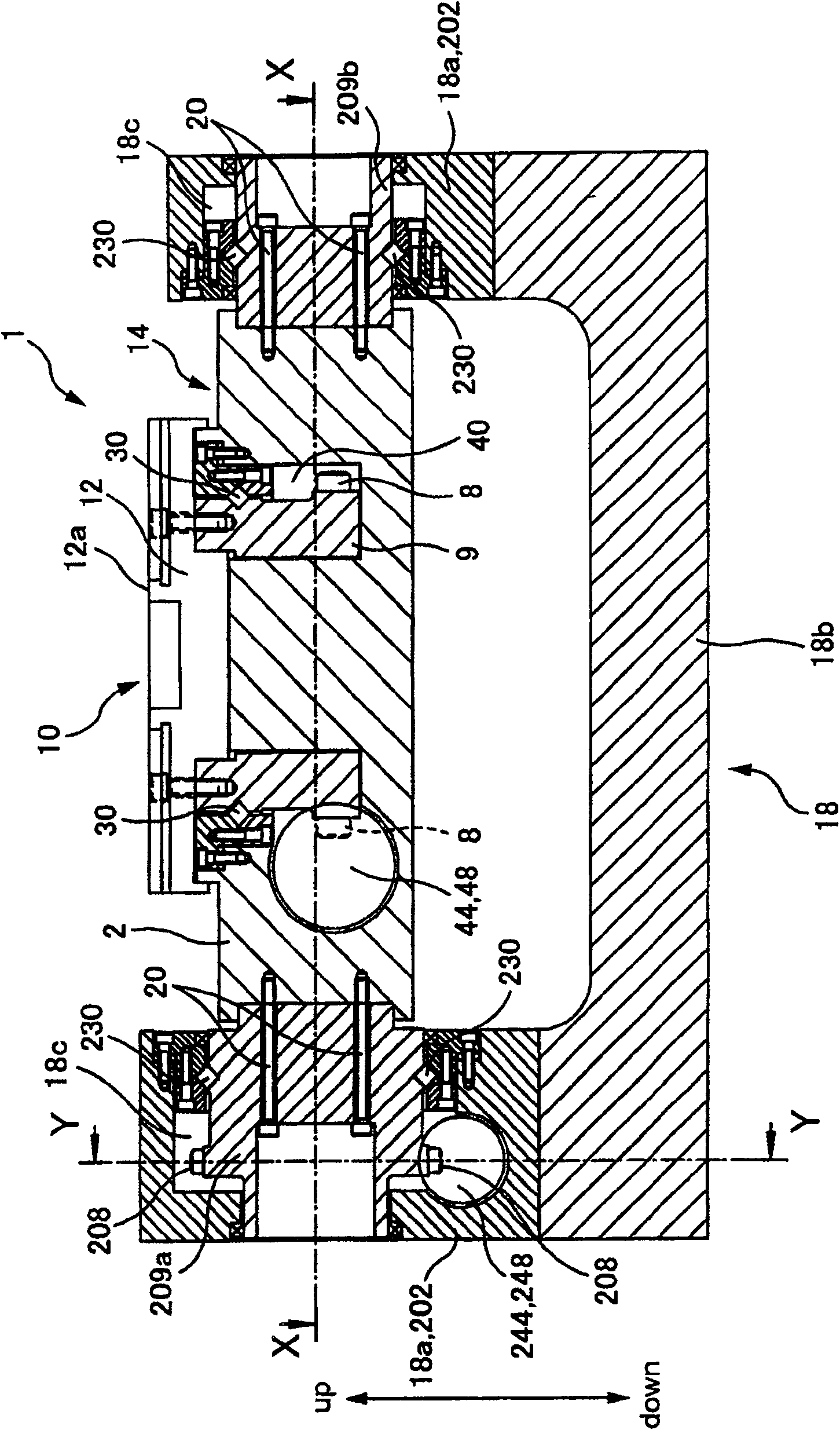
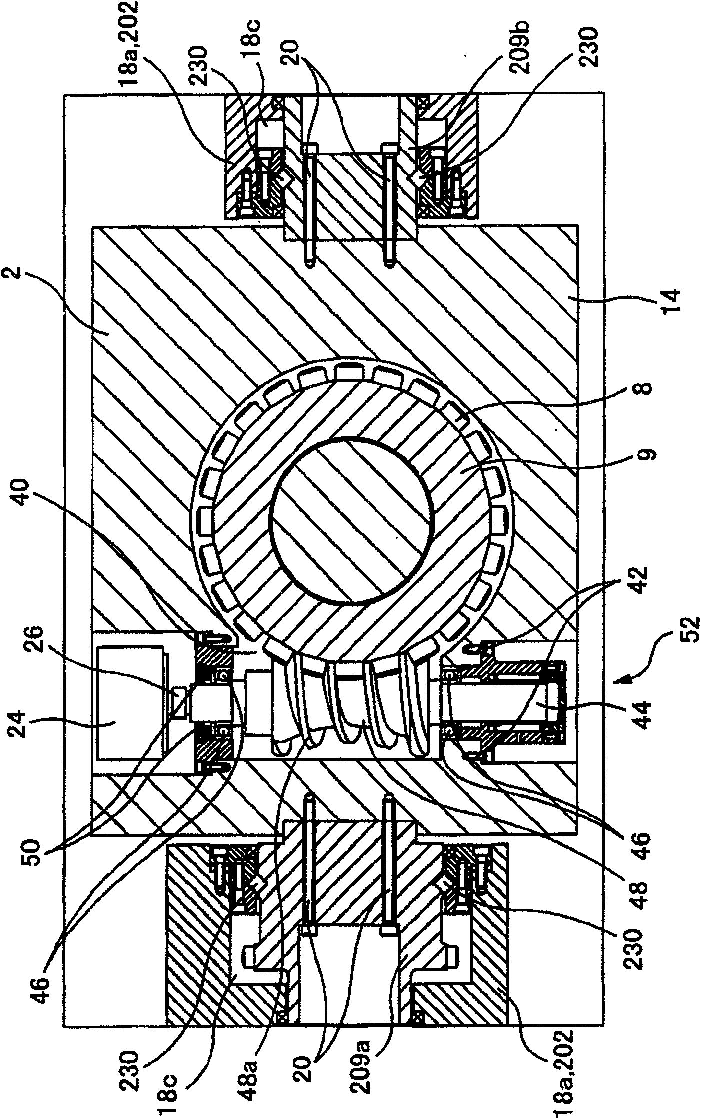
[0041] One aspect of the present invention is an inclining and rotating table apparatus (inclining and rotating table apparatus), the inclining and rotating table apparatus is provided with: a rotary table device (rotary table device), the rotary table apparatus has a driven rotating shaft, The rotation is driven by the first drive source, and the device also has a rotary table (rotary table), which is driven to rotate by the driven rotary shaft; the driven rotary shaft is used to make the rotary table device rotate by rotating the rotary table device. The surface of the table is inclined, the driven rotation shaft is driven to rotate by the second driving source; and a clamping device is used for clamping at least one of the driven rotation shaft and the driven rotation shaft.

[0042] In the above-me...


PUM

PropertyMeasurementUnit
Thicknessaaaaaaaaaa

Abstract

An inclining and rotating table apparatus is provided with: a rotary table device having a driven rotating shaft driven to rotate by a first drive source, and a rotary table driven to rotate by the driven rotating shaft; a driven turning shaft for causing inclination of a table surface of the rotary table device by causing the rotary table device to turn, the driven turning shaft being driven to turn by a second drive source; and a clamping device for clamping at least one of the driven rotating shaft and the driven turning shaft.

Description

[0001] Cross References to Related Applications [0002] This application claims priority to Japanese Patent No. 2003-357307 filed on October 17, 2003 and Japanese Patent No. 2004-293295 filed on October 6, 2004, which are incorporated herein by reference. technical field [0003] The invention belongs to the field of machine tools or similar equipment, and in particular relates to a tilting rotary table device which can be used in the field of machine tools or similar equipment. Background technique [0004] Tilt-turn table arrangements for machine tools and the like are already known. This tilt-turn table device has: a driven rotation shaft that is driven to rotate by a drive source such as a motor or the like; and a swivel table device that is driven to rotate by the driven rotation shaft. The rotary table device has: a driven rotary shaft that is driven to rotate by a drive source such as a motor or the like; and a rotary table for holding a workpiece or the like that i...

Claims


Application Information

Patent Timeline
IPC IPC(8): B23Q1/25B23Q16/10B23Q1/28B23Q1/52B23Q1/54B23Q5/34B23Q16/02F16D49/14
CPCY10T409/308792B23Q1/52Y10T408/5614F16D49/14Y10T409/305656B23Q16/025B23Q1/287Y10T74/1494B23Q1/5437Y10T409/30896B23Q5/341
Inventor 加藤平三郎鸟丸幸喜横江年彦
Owner SANKYO SEISAKUSHO
Why Eureka
Try Eureka