Pneumatic positioning and locking pin hook mechanism.

A positioning locking and bolt locking technology, which is applied in the direction of auxiliary devices, coatings, auxiliary welding equipment, etc., can solve the problems of difficult recovery of mold precision, difficult quality control, difficult debugging, etc., and achieves small footprint and simple structure , The effect of low manufacturing cost

Active Publication Date: 2017-02-15
江西清研扬天科技有限公司
View PDF7 Cites 7 Cited by
  • Summary
  • Abstract
  • Description
  • Claims
  • Application Information

AI Technical Summary

Problems solved by technology

During the replacement process, mechanical installation, electrical wiring, air pipe installation, etc. are required, and the efficiency is low, debugging is difficult, and the accuracy of the mold is difficult to restore. There are differences in different batches of workpieces, and the quality is not easy to control

Method used


Image

  • Pneumatic positioning and locking pin hook mechanism.
  • Pneumatic positioning and locking pin hook mechanism.
  • Pneumatic positioning and locking pin hook mechanism.

Examples


Embodiment Construction

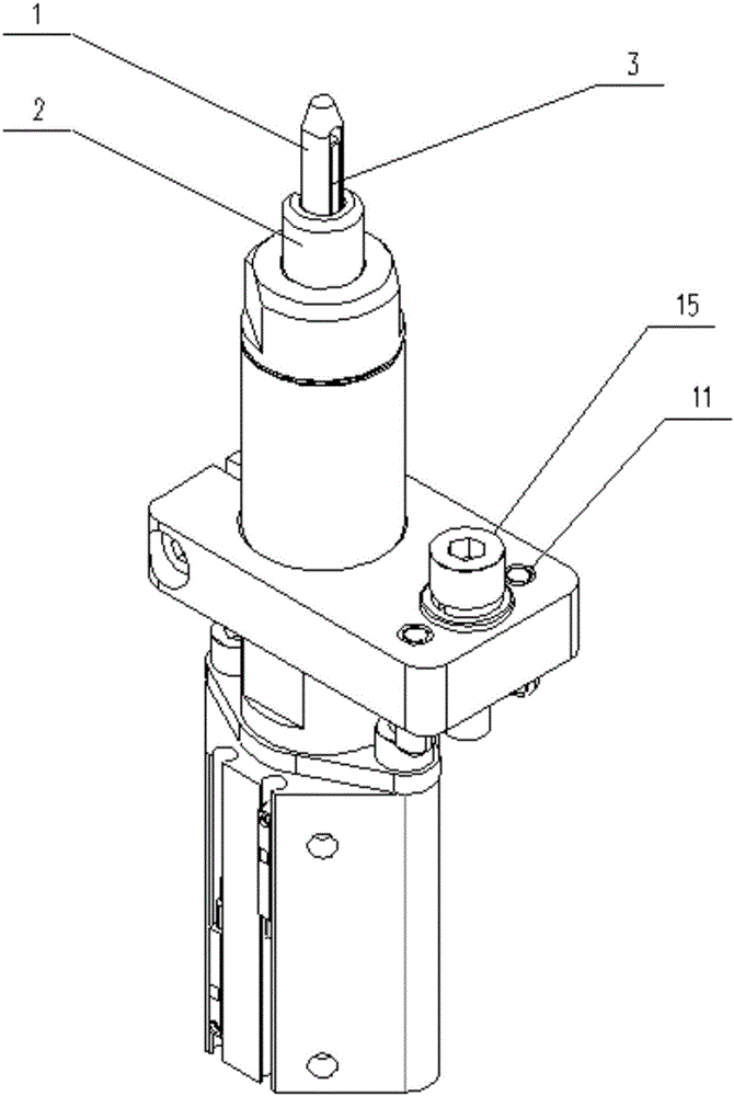
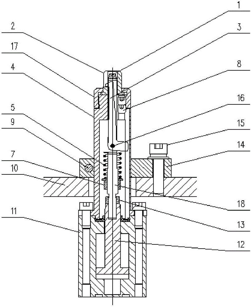
[0026] The mechanism includes: pin 1, support ring 2, hook 3, pin body 4, spring 5, spring preload nut 7, top wire 8, pin body locking bolt 9, mold mounting plate 10, cylinder 11, cylinder rod 12 , pin lock nut 13, pin body fixing plate 14, pin body fixing plate bolt 15, cylindrical pin 16, support ring gland 17, connecting rod 18;

[0027] The hook 3 is Z-shaped as a whole;

[0028] The middle part of the pin 1 has a long slot, and the "Z" hook 3 can be hidden in it; the upper part of the support ring 2 is slotted on one side, and it is aligned with the slot of the pin 1 during installation; the pin 1 and the support ring 2 are used as parts to be processed. The positioning of the component 6, the upper part of the hook 3 can extend out of the pin 1 groove from the side, and is used to lock the component 6 to be processed;

[0029] The support ring gland 17 is threadedly connected with the pin body 4, and the support ring 2 and the pin body 4 are installed together;

[0030...


PUM


Abstract

The invention provides a device facilitating achievement of clamping and positioning of various parts. The device can achieve automatic control easily, and fast switching and positioning locking between various to-be-machined parts can be performed conveniently. The production efficiency can be improved, the product quality can be improved, and the mechanism has the beneficial effects of being easy to operate, convenient to maintain, safe in production and the like and is broad in application prospect. The mechanism comprises a pin 1, a supporting ring 2, a hook 3, a pin body 4, springs 5, spring pre-tightening nuts 7, a jackscrew 8, a pin body locking bolt 9, a clamping fixture installing plate 10, a cylinder 11, a cylinder rod 12, a pin locking nut 13, a pin body fixing plate 14, a pin body fixing plate bolt 15, a cylinder pin 16, a supporting ring gland 17 and a connecting rod 18.

Description

technical field [0001] The invention relates to the field of automated manufacturing, and more specifically relates to a pin hook mechanism for quickly positioning and locking various components by using their own round holes when switching between processing stations. Background technique [0002] In the field of automated manufacturing, especially in the process of gluing and welding plastic parts and sheet metal structural parts used in the automotive, electronics, lamps and other industries, special molds are generally required. Currently used moulds, the positioning pins cannot be stretched, and the moulds at the same station can only meet the positioning of a single component. In order to switch the parts to be processed, most of the methods are to replace the parts and position the mould. During the replacement process, mechanical installation, electrical wiring, and air pipe installation are required. The efficiency is low, debugging is difficult, and the accuracy o...

Claims


Application Information

Patent Timeline
Patent Type & Authority Applications(China)
IPC IPC(8): B23K37/04B05C13/02
CPCB05C13/02B23K37/04
Inventor 白聚勇翟秀军张晓昊
Owner 江西清研扬天科技有限公司
Why Eureka
Try Eureka