
Mechanical expansion shaft and method for hoisting coil material

An expansion shaft and expansion shaft technology, which is applied in the field of mechanical expansion shafts and the lifting of coiled parts by using them, can solve the problems of large maintenance, poor reliability, and inability to bear heavy loads, etc., and achieves convenient operation, strong practicability, and structural simple effect

Active Publication Date: 2010-01-27
上海网讯新材料科技股份有限公司
View PDF8 Cites 0 Cited by
  • Summary
  • Abstract
  • Description
  • Claims
  • Application Information

AI Technical Summary

Problems solved by technology

[0004] In the prior art, for small and light foil materials, the uncoiling (unwinding) and coiling (rewinding) of coiled materials usually use air expansion shafts and optical shafts (with taper sleeves or chucks), which is very convenient, but cannot withstand heavy loads
[0005] There is also a hydraulic expansion shaft in the prior art, which must be equipped with a mobile hydraulic pump station. The oil cylinder is arranged in the expansion shaft, which is bulky, requires a lot of maintenance, is easy to leak and pollute, and has poor reliability.

Method used


Image

  • Mechanical expansion shaft and method for hoisting coil material
  • Mechanical expansion shaft and method for hoisting coil material
  • Mechanical expansion shaft and method for hoisting coil material

Examples


Embodiment 1

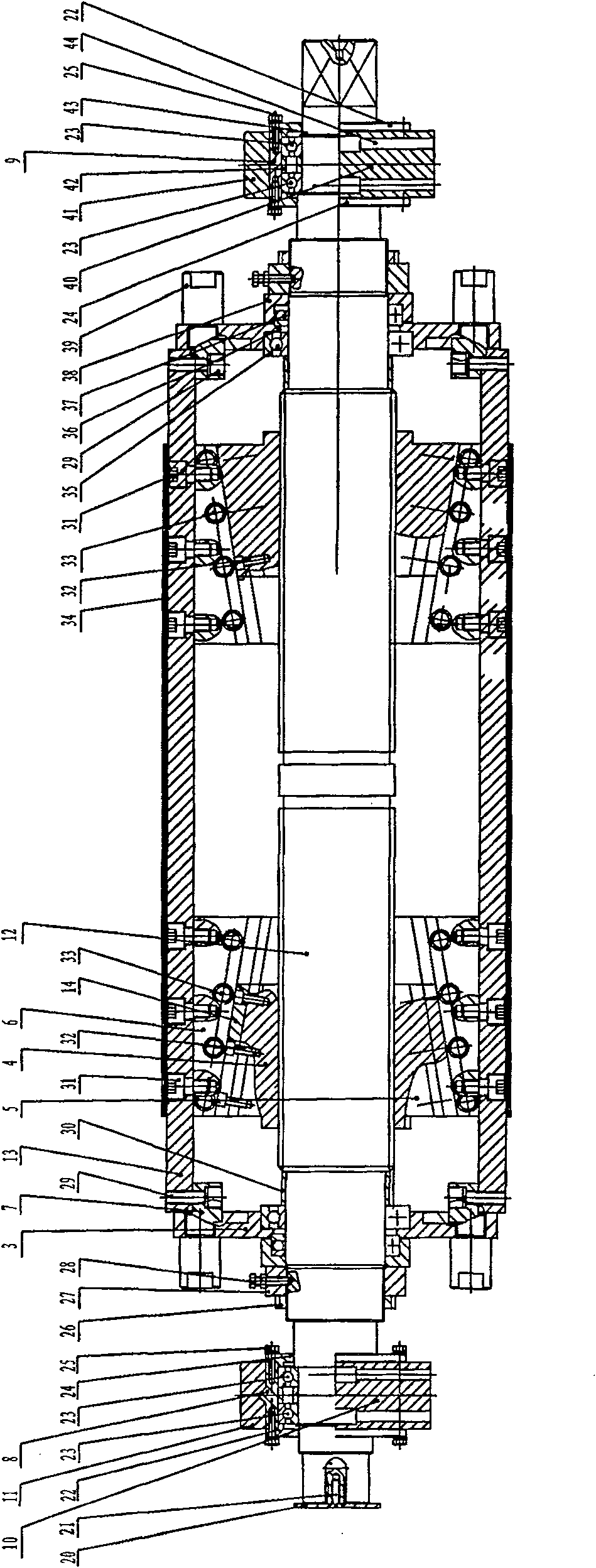
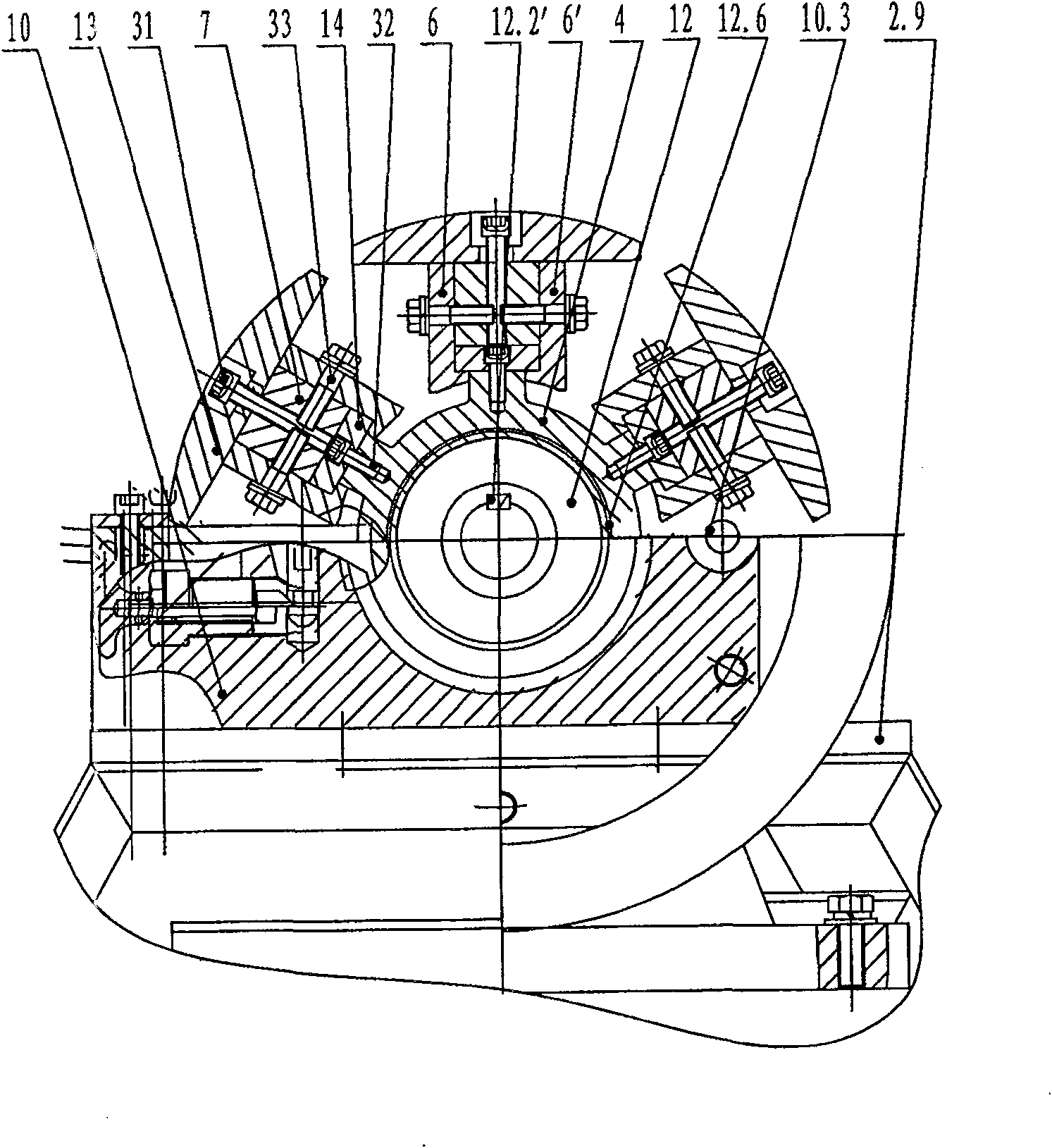
[0049] A specific embodiment of the mechanical expansion shaft of the present invention, such as figure 1 and figure 2 as shown, figure 1 is a longitudinal sectional view of the mechanical expansion shaft of the present invention, figure 2 It is a transverse sectional view of the mechanical expansion shaft of the present invention. As can be seen from the figure, its main structure is as follows:

[0050] The mechanical expansion shaft in this embodiment includes a mandrel 12 and an expansion shaft support plate 13. One end of the mandrel 12 is provided with a square block, and the middle part of the mandrel 12 is symmetrically provided with two sections of external threads with opposite directions of rotation. An expansion shaft nut 4 is sleeved respectively. The overall expansion shaft nut 4 is in the shape of a truncated cone. The inner wall of the expansion shaft nut 4 is provided with an internal thread corresponding to the external thread on the mandrel 12. The out...

Embodiment 2

[0068] A specific embodiment of the mechanical expansion shaft of the present invention has the following structure:

[0069] A mechanical expansion shaft, including a mandrel and an expansion shaft support plate, one end of the mandrel is provided with a square block, and the middle of the mandrel is symmetrically provided with two sections of external threads with opposite rotation directions, and each external thread is respectively sleeved with an expansion thread The outer wall of the expansion shaft nut is a cone-column structure, and the inner wall is provided with an internal thread corresponding to the external thread on the mandrel. The two expansion shaft nuts are arranged symmetrically. The outer wall of the expansion shaft nut is equipped with multiple Tilt sliding mechanism on the silk nut.

[0070] The structure of the inclined sliding mechanism in this embodiment is as follows: a plurality of inverted T-shaped grooves are arranged on the outer wall of the expan...


PUM


Abstract

The invention relates to a mechanical expansion shaft, comprising a core shaft and an expansion shaft supporting plate; the middle part of the core shaft is symmetrically provided with two sections of external threads with the reverse rotation directions; the external thread is respectively sleeved by an expansion shaft thread; the internal wall of the expansion shaft thread is an internal thread and the external wall thereof is a truncated cone shape; the external wall thereof is provided with a plurality of oblique sliding mechanisms; the external sides of two oblique sliding mechanisms are fixed with the expansion shaft supporting plates; a plurality of expansion shaft supporting plates are composed of the external wall of the cylinder by surrounding the core shaft; the end of each expansion shaft supporting plate is fixed with a side sliding block; the end part of the core shaft is provided with two baffles; the internal bearing chamber of the baffle is clamped by a rolling bearing; the external bearing chamber is clamped by a push ball bearing; the external side of the pushing ball bearing is a bearing seat sleeve which is fixed on the core shaft by a locking sleeve; the external side of the baffle is fixed with a triggering pin; the internal side of the triggering plate is provided with a radial side sliding trough; the side sliding block is movably clamped inside the side sliding trough. The mechanical expansion shaft of the invention has the advantages of simple structure, convenient operation and wide application field.

Description

technical field [0001] The invention relates to shafts, in particular to a movable mechanical expansion shaft. On the basis of the existing expansion shaft, the present invention makes full use of the mechanical principle and realizes the manufacture and application of the expansion shaft with a simple structure. Background technique [0002] In the prior art, for large and heavy foil materials, fixed cantilever expansion shafts (hydraulic or pneumatic) are usually used for uncoiling (unwinding) and coiling (rewinding) of coiled materials. The roll is sent to the expansion shaft by other means or device mechanisms, which is very complicated and expensive. [0003] In the prior art, there is a utility model patent "Expansion Shaft" with the patent number of 02265497.6, which involves the expansion shaft. This type of expansion shaft mainly includes an outer shaft sleeve, a telescopic block and a telescopic mechanism. The telescopic mechanism includes a pull rod and an adjust...

Claims


Application Information

Patent Timeline
Patent Type & Authority Patents(China)
IPC IPC(8): B65H75/08B65H75/24B65H16/02B65H18/02B65H19/12B65H19/30B66C13/08
Inventor 付瑞英孙继光苏彭恩赵先锋
Owner 上海网讯新材料科技股份有限公司
Learn More