Rotary atomizing painting device

一种旋转雾化、涂装的技术,应用在喷雾放电装置、喷射装置、静电喷射装置等方向,能够解决涂敷图案狭窄、涂装时间缩短、不能有效地实现涂敷图案扩大等问题,达到实现微粒化的效果

Inactive Publication Date: 2013-05-08
TOYOTA JIDOSHA KK +1
View PDF4 Cites 16 Cited by
  • Summary
  • Abstract
  • Description
  • Claims
  • Application Information

AI Technical Summary

Problems solved by technology

[0004] However, in the conventional rotary atomization coating device, there are the following problems: if the coating pattern of the paint is given priority, it is difficult to realize the micronization of the paint;
[0009] However, the rotary atomization coating device described in Patent Document 1 is a rotary atomization coating device for metal coating. The coating pattern is expanded, but the coating pattern is still narrow compared with the rotary atomization coating equipment used in general electrostatic coating, so the shortening of the coating time cannot be fully realized
In addition, in such a rotary atomization coating device, even if the flow rate of the molding gas is further increased, the expansion of the coating pattern cannot be effectively achieved.
[0010] Therefore, can be used in general electrostatic coating and can realize the atomization of coating while the rotary atomization coating device of expanding the coating pattern of coating remains to be developed.

Method used


Image

  • Rotary atomizing painting device
  • Rotary atomizing painting device
  • Rotary atomizing painting device

Examples


Embodiment Construction

[0030] Next, embodiments of the present invention will be described.

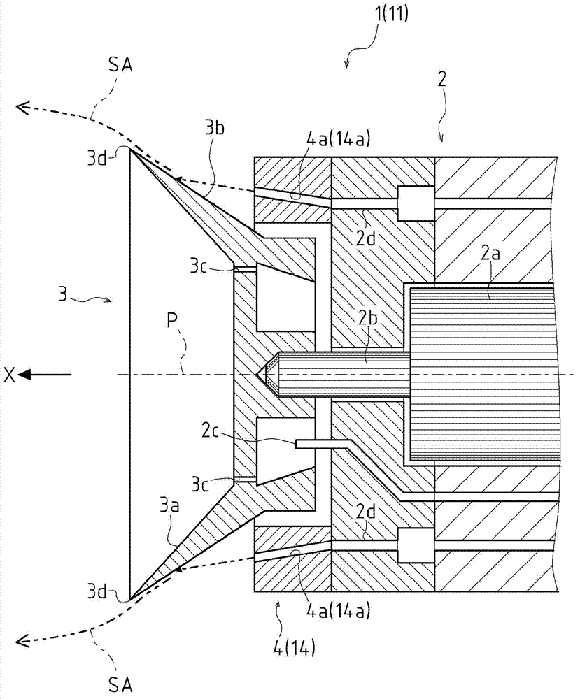
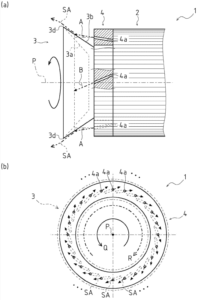
[0031] First, refer to Figure 1 to Figure 4 The overall configuration of the rotary atomization coating device according to the first embodiment of the present invention will be described. Additionally, the figure 1 The direction of the arrow X shown in , is defined as the spraying direction of the paint, that is, the front, and the following description will be made.

[0032] Such as figure 1 As shown, the coating gun 1 as the rotary atomization coating device according to the first embodiment of the present invention is a coating device for spraying atomized paint on an object to be coated used in electrostatic coating, and includes a gun main body 2 , rotary cup 3, forming air ring 4.

[0033] The gun body 2 is supported by a manipulator (not shown) for displacing the coating gun 1 in a desired position and posture, and is provided with a rotary cup 3 and / or a forming air ring 4, and an air motor 2a...


PUM


Abstract

The rotary atomizing painting device is provided with a bell cup (3) disposed at the most front part in the paint spray direction X and axially supported by a rotating shaft (2b) and a shaping air ring (4) disposed rearward of this bell cup (3) in the paint spray direction and in which a plurality of discharge openings (4a) is formed on the periphery centered on the rotating shaft (2b). The plurality of discharge openings (4a) is formed such that the axial direction of the plurality of discharge openings (4a) is in a direction and a slant to the rotating shaft (2b). The axial direction of the plurality of discharge openings (4a) is formed to aim at a back surface part (3b), which is a part on the back surface side of the bell cup (3) from the paint spray direction.

Description

technical field [0001] The present invention relates to a technique of a rotary atomization type coating device used in electrostatic coating. Background technique [0002] Conventionally, a so-called rotary atomization coating device is known as a coating device for electrostatically coating a body of an automobile or the like. [0003] In recent years, in the rotary atomization coating apparatus, there is a need to further shorten the coating time, but the shortening of the coating time by operating the coating robot at a higher speed is approaching the limit. Therefore, research is underway to shorten the painting time by enlarging the paint application pattern while making the operation speed of the painting robot comparable to conventional ones. If the paint application pattern can be expanded, the amount of overlap can be increased compared to the past, so the moving distance of the painting robot is shorter than before, and the coating time can be shortened. [0004...

Claims


Application Information

Patent Timeline
Patent Type & Authority Applications(China)
IPC IPC(8): B05B5/03B05B5/04
CPCB05B5/03B05B5/0426B05B5/0407B05B3/1007B05B3/1042
Inventor 山崎勇三井三千雄横沟义治细田俊男
Owner TOYOTA JIDOSHA KK
Why Eureka
Try Eureka