Circular fluorescent lamp and lighting apparatus

A fluorescent lamp and annular technology, which is applied in the field of annular fluorescent lamps, can solve the problems of different positioning accuracy, unsimple structure, discrete rotation limit angle of the lamp head, etc., and achieves the effect of improving the easiness and the simple structure.

Inactive Publication Date: 2010-03-17
TOSHIBA LIGHTING & TECH CORP
View PDF4 Cites 0 Cited by
  • Summary
  • Abstract
  • Description
  • Claims
  • Application Information

AI Technical Summary

Problems solved by technology

[0003] Therefore, the lamp cap can be rotated relative to the lamp tube by an angle at which the lamp cap protrusion can move between the restricting members on both sides, but the rotation beyond this angle can be restricted.
[0004] However, there is such a problem in this existing annular fluorescent lamp, that is, it is necessary to fix the restricting member in the annular concave portion of at least one of the two ends of the annular lamp tube, and set the limit member on the lamp cap toward these The protrusion protruding from the gap between the restricting parts is not simple in structure, and there is a problem that the rotation restricting angle of the lamp cap tends to be scattered due to the difference in positioning accuracy between these restricting parts and the protrusions.

Method used


Image

  • Circular fluorescent lamp and lighting apparatus
  • Circular fluorescent lamp and lighting apparatus
  • Circular fluorescent lamp and lighting apparatus

Examples


Embodiment Construction

[0032] Hereinafter, embodiments of the present invention will be described with reference to the accompanying drawings. In these drawings, parts that are identical or equivalent to each other have the same reference numerals.

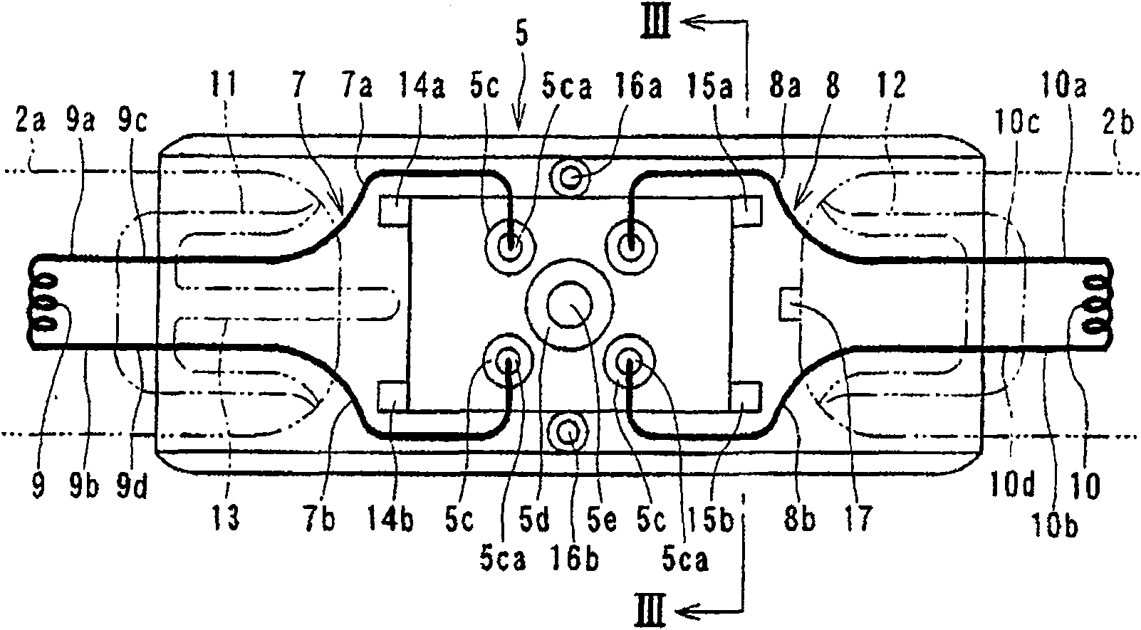
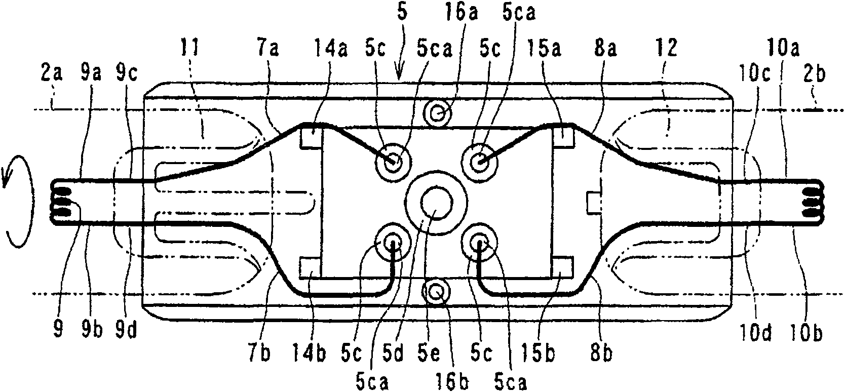
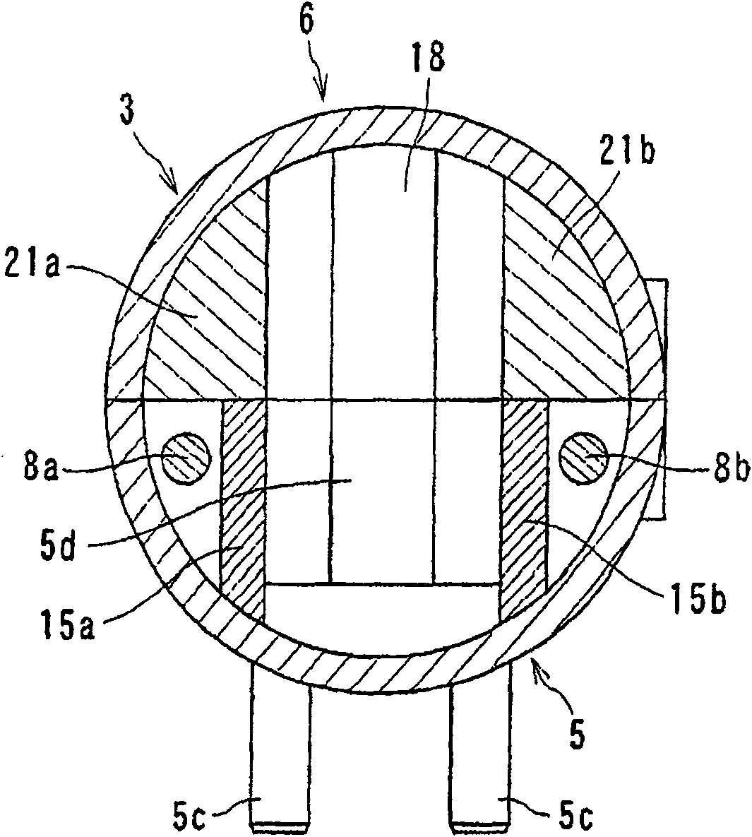
[0033] figure 1 It is an enlarged cross-sectional view showing a base portion of a circular fluorescent lamp according to an embodiment of the present invention, showing a state before the base is rotated, figure 2 Shows the state when rotation is restricted. Figure 3 to Figure 10 It is a drawing showing the overall structure of the circular fluorescent lamp and the structure of the main body of the lamp holder.

[0034] Figure 4 Shown is a ring-shaped fluorescent lamp formed in a square shape on the same plane. In this ring-shaped fluorescent lamp 1, two end portions 2a, 2b of a lamp tube 2 made of glass are arranged to face each other with a required interval. On the outer surface of 2b, the hollow cylindrical base 3 attached across these two e...


PUM


Abstract

A circular fluorescent lamp comprising: a circular bulb (2) that includes a pair of filament electrodes (9,10) respectively sealed at the opposite ends (2a,2b), a fluorescent substance layer formed onthe inner surface, and a discharge medium sealed inside, and is formed to be circular so that the opposite ends face each other; and a base that includes outer leads (7a,7b,8a,8b) respectively extending to the outside from the opposite ends of the bulb, a hollow, cylindrical base body (5) rotatably provided along the outer surface of the bulb to extend between the opposite ends of the bulb, basepins (5c,5c,---) disposed on the outer surface of the bulb body and connected with the outer leads, and lead wire regulating units (14a,14b,15a,15b) provided in the base body so as to route the outerleads to be mutually separated in a base-diameter direction and regulating the rotation angle of the base body. According to the above arrangement, a circular fluorescent lamp and a lighting apparatusare provided that can regulate the rotation angle of the base to within specified range without forming, as a base rotation angle regulating means, a regulating member such as a protrusion on the bulb side.

Description

technical field [0001] The present invention relates to an annular fluorescent lamp with a lamp base that can rotate at a predetermined angle relative to an annular lamp tube, and a lighting fixture with the annular fluorescent lamp. Background technique [0002] Conventionally, as an example of such a circular fluorescent lamp, there is a fluorescent lamp described in Japanese Patent Application Laid-Open No. 11-162329. In the annular fluorescent lamp described therein, an annular concave portion (reduced diameter portion) is formed on one of both ends of an annular glass lamp tube with a cap embedded therein, and the annular concave portion is fixed at a required interval in the circumferential direction There are a plurality of restricting members, and on the inner surface of the base, a protrusion protruding between these restricting members is provided. [0003] Therefore, the base can be rotated with respect to the lamp tube by an angle at which the protrusions of the...

Claims


Application Information

Patent Timeline
Patent Type & Authority Patents(China)
IPC IPC(8): H01J5/50F21S4/00F21Y103/02
CPCH01J5/565H01J61/322H01J61/36H01J2893/0002
Inventor 泉昌裕吉田正彦
Owner TOSHIBA LIGHTING & TECH CORP
Why Eureka
Try Eureka