
Moisture proof power cabinet

A technology for power cabinets and cabinets, which is applied in the direction of substation/distribution device casing, substation/switchgear cooling/ventilation, etc., can solve the problems of wind blocking and rainwater inflow, and achieves improved safety and moisture removal efficiency. , the effect of improving the air discharge efficiency

Inactive Publication Date: 2019-01-18
STATE GRID CORP OF CHINA +1
View PDF7 Cites 0 Cited by
  • Summary
  • Abstract
  • Description
  • Claims
  • Application Information

AI Technical Summary

Problems solved by technology

[0007] In view of this, the purpose of the present invention is to provide a moisture-proof power cabinet for the deficiencies of the prior art. The application designs the structure of the lower air inlet, which can effectively prevent humid air from entering the cabinet from the lower air inlet. The air flow way out from the bottom solves the problems of windshield and rainwater infusion in the prior art

Method used


Image

  • Moisture proof power cabinet
  • Moisture proof power cabinet
  • Moisture proof power cabinet

Examples


Embodiment 1

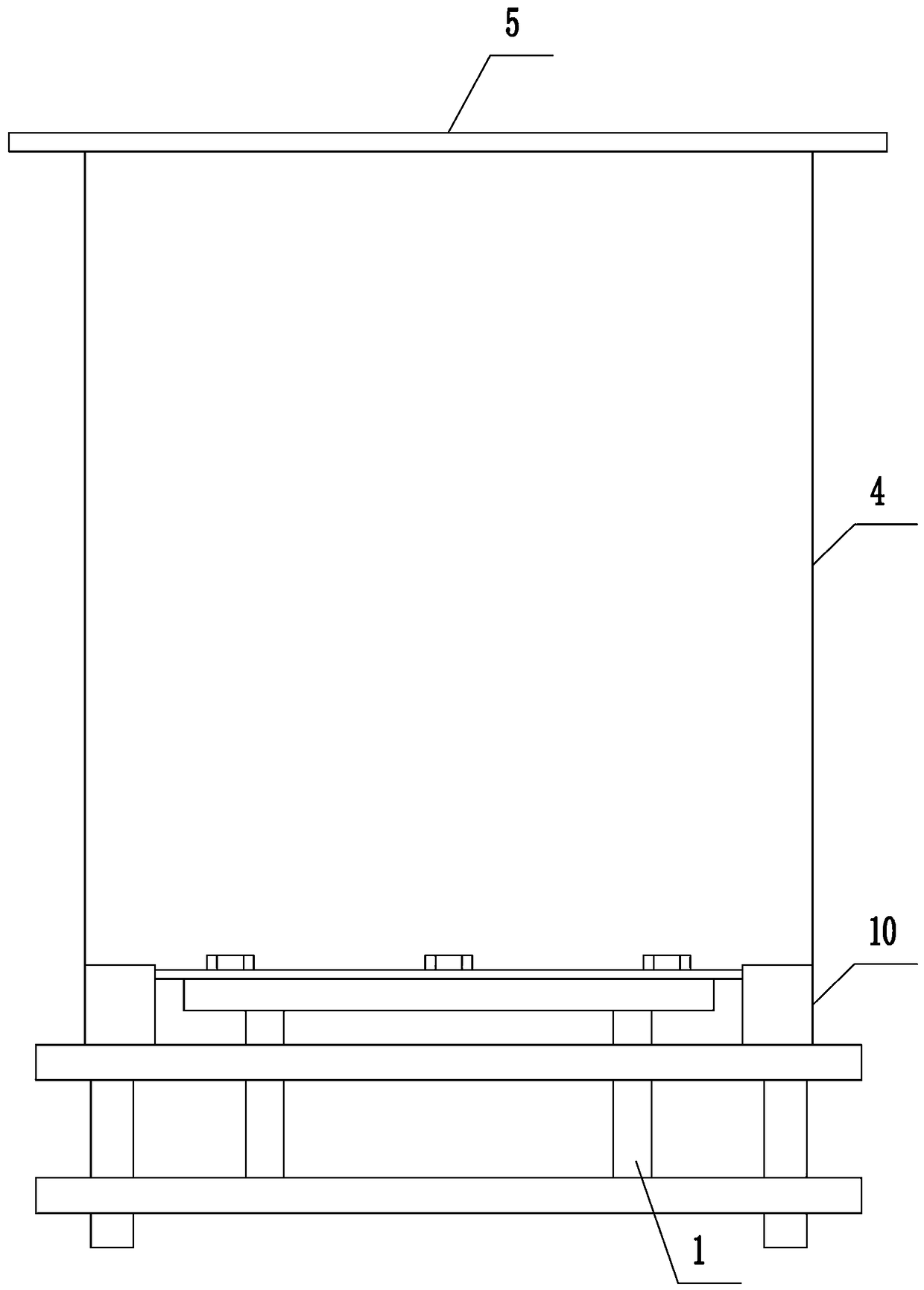
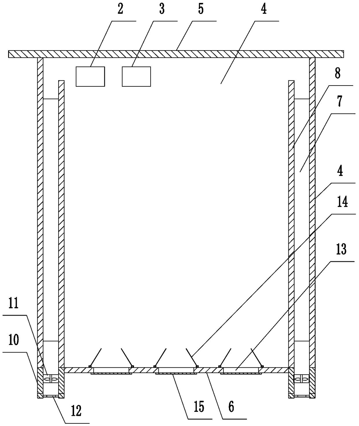
[0032] like Figure 1 to Figure 3 As shown, the present invention discloses a moisture-proof power cabinet, which includes a cabinet body and a bracket 1 arranged at the lower end of the cabinet body. The bracket 1 adopts a frame structure welded by angle steel. The electrically connected humidity sensing module 2 and the central processing module 3, the central processing module 3 adopts the main control element of the prior art, such as a single-chip microcomputer;

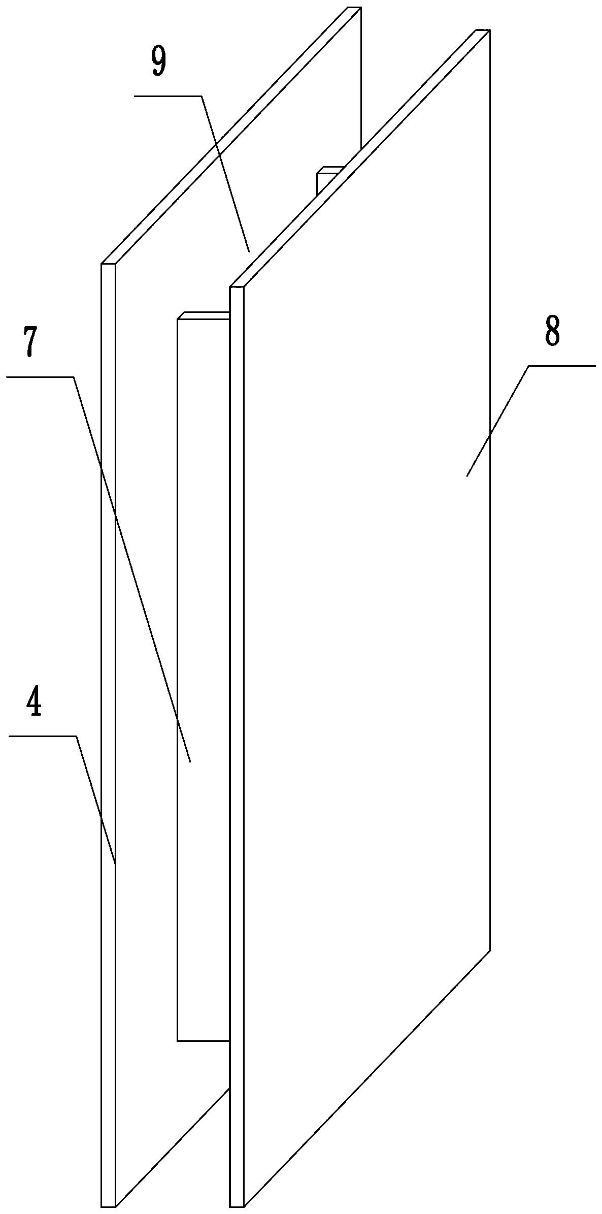
[0033] The cabinet is provided with a plurality of lower air inlets 13 and lower air outlets 12, specifically: the cabinet includes two outer baffles 4, a top plate 5, a bottom 6, a front baffle and a rear baffle, and the inner sides of the two outer baffles 4 Both are fixedly connected to the inner baffle plate 8 through the connecting rib 7, such as image 3As shown, the connecting rib 7 is vertically arranged as two, and the connecting rib 7 divides the cavity formed between the outer baffle plate 4 and the ...

Embodiment 2

[0036] The structure of this embodiment is basically the same as that of Embodiment 1, the difference is: as Figure 5 As shown, the four edges of the top plate 5 are provided with water retaining plates 16, the top plate 5 is provided with drain holes, and the drain holes are provided with drain pipes 17.

Embodiment 3

[0038] The structure of this embodiment is basically the same as that of Embodiment 2, the difference is: as Image 6 As shown, a flange plate 18 is arranged on the edge of the bottom plate 6, and the flange plate 18 is fixedly connected to the bracket 1 by bolts. A disc spring assembly 19 is arranged between the flange plate 18 and the bracket 1, and the disc spring assembly 19 is sleeved on the outside of the bolt.

[0039] In this embodiment, a disc spring assembly is arranged between the cabinet body and the bracket, which can effectively alleviate the impact force of the micro-seismic process that occurs when the internal components of the power cabinet are working, and improve the stability and safety of the use process.


PUM


Abstract

The invention belongs to the related technical field of an intelligent electric meter, in particular to a moisture-proof electric cabinet. The moisture-proof electric cabinet comprises a cabinet bodyand a bracket arranged at the lower end of the cabinet body; the cabinet body is provided with a plurality of lower air inlets and lower air outlets; the inner side of the lower air inlets is hinged with a sealing mechanism; and the sealing mechanism comprises two semicircular baffles. As that application design the structure of the lower air inlet, the invention can effectively prevent the wet air from enter the cabinet from the lower air inlet, adopts the air flow mode of the lower air inlet and the low air outlet, and solves the problems of wind shielding and rainwater pouring in the priorart.

Description

technical field [0001] The invention belongs to the technical field related to smart meters, in particular to a moisture-proof power cabinet. Background technique [0002] The power switch cabinet is a kind of electrical equipment. The outside line of the power switch cabinet first enters the main control switch in the cabinet, and then enters the sub-control switch, and each branch is set according to its needs. Such as instruments, automatic controls, motor magnetic switches, various AC contactors, etc., some also have high-voltage room and low-voltage room switch cabinets, high-voltage busbars, such as power plants, etc. load shedding. The main function of the power switchgear is to open and close, control and protect electrical equipment during the process of power generation, transmission, distribution and power conversion in the power system. The components in the power switch cabinet are mainly composed of circuit breakers, isolating switches, load switches, operati...

Claims


Application Information

Patent Timeline
Patent Type & Authority Applications(China)
IPC IPC(8): H02B1/56H02B1/30
Inventor 南钰宋瑞卿宋丽华陈鹏胡江雪姬晓利张丽
Owner STATE GRID CORP OF CHINA
Learn More