Heat dissipation electric meter box

A technology of meter box and box body, applied in the direction of measuring electrical variables, measuring devices, instruments, etc., can solve the problems of filling, wind blocking, etc., and achieve the effect of improving flow efficiency and improving safety

Inactive Publication Date: 2018-11-23
STATE GRID CORP OF CHINA +1
View PDF6 Cites 9 Cited by
  • Summary
  • Abstract
  • Description
  • Claims
  • Application Information

AI Technical Summary

Problems solved by technology

[0007] In view of this, the purpose of the present invention is to provide a heat dissipation meter box for the deficiencies of the prior art. The present invention adopts the air flow mode of bottom-in and bottom-out, which solves the problems of wind protection and rainwater pouring in the prior art. And the entire air flow runs through the entire space in the box from bottom to top, making full use of the rising buoyancy of the hot air generated by the electric energy meter to improve the flow efficiency of the gas in the box

Method used


Image

  • Heat dissipation electric meter box
  • Heat dissipation electric meter box
  • Heat dissipation electric meter box

Examples


Embodiment 1

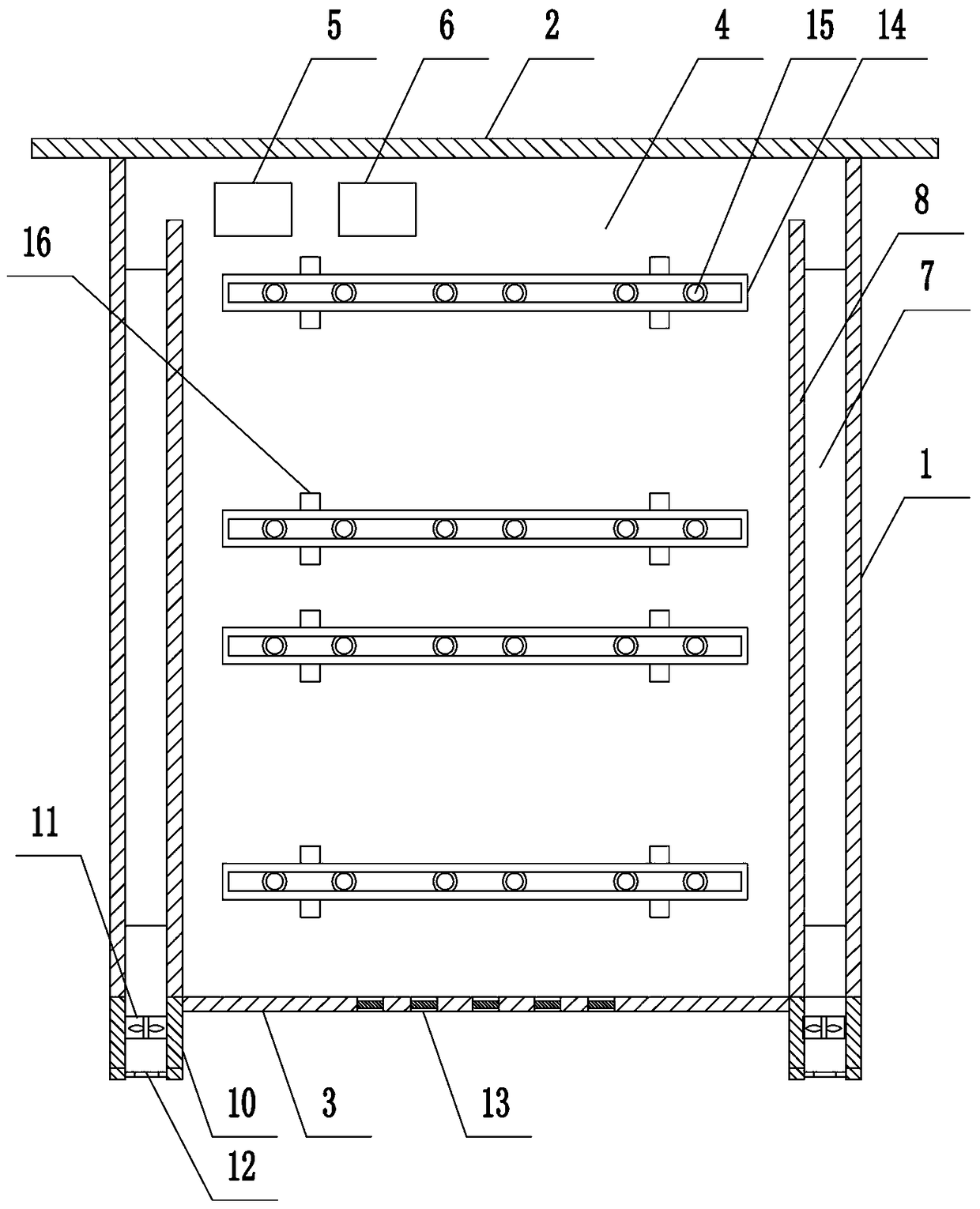
[0030] like figure 1 As shown, the present invention includes a box body, the box body includes two left and right outer baffles 1, a top plate 2, a bottom plate 3, a front baffle and a rear baffle 4, and a temperature sensing module 5 and a central processing module electrically connected in sequence are arranged in the box. 6. The central processing module 6 adopts the main control element of the prior art, such as a single-chip microcomputer, and the inner sides of the two outer baffles 1 are fixedly connected to the inner baffle 8 through the connecting ribs 7;

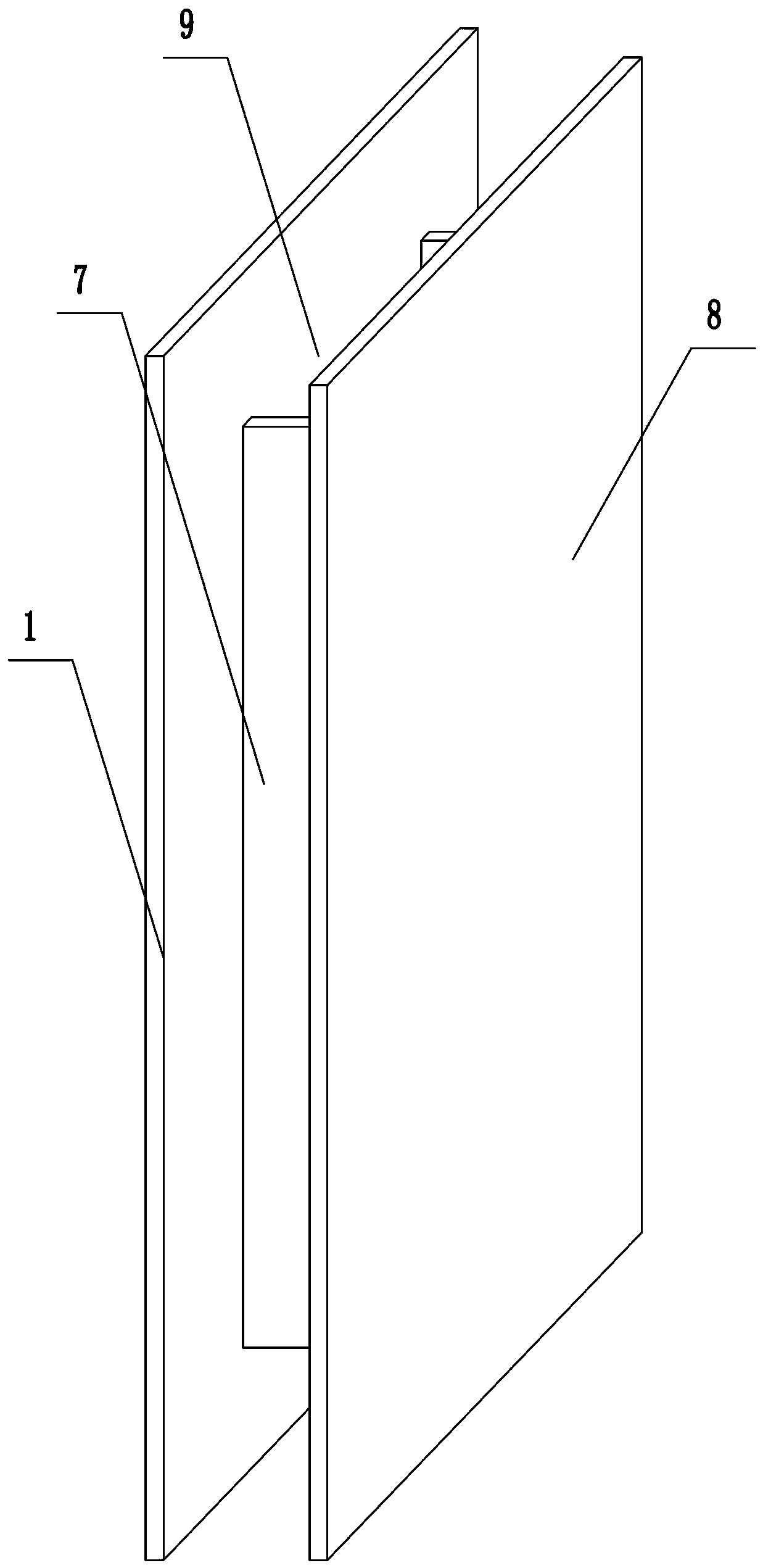
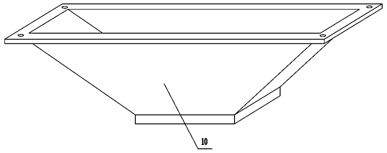
[0031] like figure 2 As shown, in this embodiment, the connecting ribs 7 are vertically divided into two, and the connecting ribs 7 divide the cavity formed between the outer baffle 1 and the inner baffle 8 into three airflow channels 9, and the upper ends of the three airflow channels 9 Connected with the inner space of the box body, the lower end of the airflow channel 9 is provided with a gas collecting shell...

Embodiment 2

[0035] combine Figure 1 to Figure 4 , the present invention includes a box body, the box body includes two left and right outer baffles 1, a top plate 2, a bottom plate 3, a front baffle and a rear baffle 4, the four edges of the top plate 2 are provided with water baffles 17, and the top plate 2 is provided with drainage A drain pipe 18 is arranged in the drainage hole, and a temperature sensing module 5 and a central processing module 6 are arranged in the box which are electrically connected in sequence. The inner sides of the two outer baffles 1 are fixedly connected to the inner baffle 8 through the connecting ribs 7. The connecting ribs 7 are vertically divided into two ( figure 2 shown), the connecting rib 7 divides the cavity formed between the outer baffle 1 and the inner baffle 8 into three air flow channels 9, the upper ends of the three air flow channels 9 are connected with the inner space of the box, and the air flow channels 9 The lower end is provided with a...


PUM


Abstract

The invention belongs to the technical field of electric power intelligent equipment, and particularly relates to a heat dissipation electric meter box. The electric meter box comprises a box body which comprises a left outer side baffle plate, a right outer side baffle plate, a top plate, a bottom plate, a front baffle plate and a rear baffle plate, and the inner sides of the two outer baffle plates are fixedly connected with the inner baffle plates through one or more connecting ribs vertically arranged. A cavity formed by outer side baffle plates of the connecting ribs and inner side baffleplate are divided into a plurality of air flow channels, of which the upper ends communicate with the inner space of the box body, and the lower ends are provided with a gas collecting shell. An exhaust fan and an air outlet are fixedly arranged in the air collecting shell, and an air inlet is formed in the bottom plate. According to the electric meter box, an air flowing mode of downward inlet and downward outlet is adopted, so that the functions of wind blocking and rainwater filling prevention are achieved. The whole air flow penetrates through the whole space in the box body from bottom to top, the rising buoyancy of hot air generated by the electric energy meter is fully utilized, and the flowing efficiency of air in the box body is improved.

Description

technical field [0001] The invention belongs to the technical field of electric power intelligent equipment, in particular to a heat-dissipating electric meter box. Background technique [0002] Electricity meter is an instrument used to measure electric energy, also known as watt-hour meter, fire meter, electric energy meter, kilowatt-hour meter, and is widely used in the electric power industry. As a terminal instrument that counts users' electricity consumption, its working environment needs to be set in strict accordance with regulations. In rural power grid coverage areas, electric energy meters are often installed in outdoor meter boxes. [0003] In order to prevent the natural environment from affecting the normal operation of the meter, the meter box needs to be specially designed, such as waterproof, moisture-proof and other functions. [0004] For example, the patent document of the authorized publication number CN207703907U discloses an electric meter box with fa...

Claims


Application Information

Patent Timeline
Patent Type & Authority Applications(China)
IPC IPC(8): G01R11/04
CPCG01R11/04
Inventor 南钰赵鑫宋瑞卿王磊高天里陈鹏胡江雪
Owner STATE GRID CORP OF CHINA
Why Eureka
Try Eureka