Air flow arrangement for a reduced-emission single cylinder engine

a single-cylinder engine and air flow arrangement technology, applied in the field of engines, can solve the problems of difficult integration of other more sophisticated technologies into small engines, high cost, etc., and achieve the effect of improving air-fuel mixing and properly calibrating

Inactive Publication Date: 2006-02-23
BRIGGS & STRATTON
View PDF57 Cites 10 Cited by
  • Summary
  • Abstract
  • Description
  • Claims
  • Application Information

AI Technical Summary

Benefits of technology

[0003] The present invention provides an air flow arrangement for a reduced-emission, single cylinder engine th

Problems solved by technology

These or other more sophisticated technologies are diffi

Method used


Image

  • Air flow arrangement for a reduced-emission single cylinder engine
  • Air flow arrangement for a reduced-emission single cylinder engine
  • Air flow arrangement for a reduced-emission single cylinder engine

Examples


Embodiment Construction

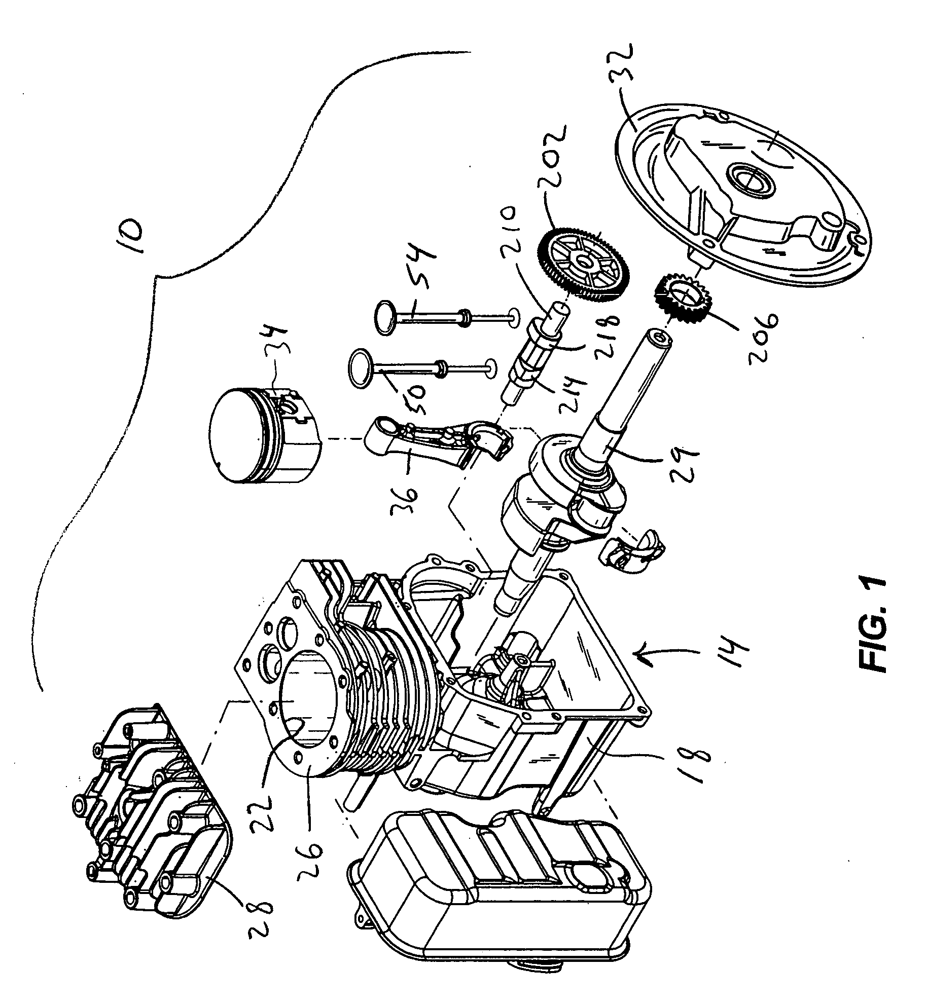
[0021]FIGS. 1-12 illustrate various features and aspects of a reduced-emission, four-cycle, single cylinder engine 10 (only a portion of which is shown). Such a “small” engine 10 may be configured with a power output as low as about 1 Hp and as high as about 20 Hp to operate engine-driven outdoor power equipment (e.g., lawn mowers, lawn tractors, snow throwers, etc.). The illustrated engine 10 is configured as an approximate 3.5 Hp single-cylinder, air-cooled engine having a displacement of about 9 cubic inches. The illustrated engine 10 is also configured as a vertical shaft engine, however, the engine 10 may also be configured as a horizontal shaft engine.

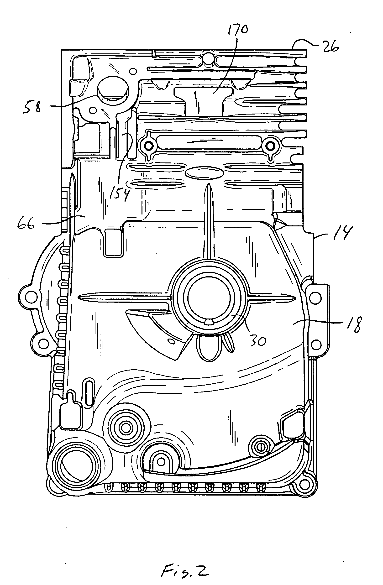
[0022] With reference to FIG. 1, the engine 10 includes an upper engine housing 14 which may be formed as a single piece by any of a number of different processes (e.g., die casting, forging, etc.). The engine housing 14 generally includes a crankcase 18 containing lubricant and a cylinder bore 22 extending from the crankcase 18...


PUM


Abstract

The present invention provides a reduced emission, single cylinder engine incorporating an air flow arrangement for improving flow efficiency of the intake air drawn into the engine and the exhaust discharged from the engine.

Description

FIELD OF THE INVENTION [0001] This invention relates generally to engines, and more particularly to low-cost, single cylinder engines. BACKGROUND OF THE INVENTION [0002] Government regulations pertaining to exhaust emissions of small engines, such as those utilized in lawnmowers, lawn tractors, string trimmers, etc., have become increasingly strict. More particularly, such regulations govern the amount of hydrocarbons and nitrous oxides exhausted by the engine. Currently, several different engine technologies are available for decreasing hydrocarbon emissions, such as, for example, sophisticated fuel injection systems and exhaust catalyst devices. These or other more sophisticated technologies are difficult to incorporate into small engines and are expensive. SUMMARY OF THE INVENTION [0003] The present invention provides an air flow arrangement for a reduced-emission, single cylinder engine that improves air-fuel mixing in a carbureted engine, and enables the air-fuel mixture to be ...

Claims


Application Information

Patent Timeline
IPC IPC(8): F02F1/42
CPCF02B2275/22F02F3/00F02F1/4285
Inventor PROCKNOW, DAVE
Owner BRIGGS & STRATTON
Why Eureka
Try Eureka