Particulate flow sensing for an agricultural implement

a technology of agricultural implements and air, applied in the field of mass flow sensors, can solve problems such as productivity reduction, and achieve the effect of reducing calibration delays and more accurate seeding and fertilization rates

Active Publication Date: 2013-08-06
DEERE & CO
View PDF40 Cites 71 Cited by
  • Summary
  • Abstract
  • Description
  • Claims
  • Application Information

AI Technical Summary

Benefits of technology

[0003]To eliminate a manual calibration step, a mass flow rate sensor is placed in the air stream of an air seeder or similar implement that conveys materials such as seed and fertilizer. The mass flow rate sensor reduces calibration delays and provides more accurate seeding and fertilizing rates, even when the seed and fertilizer are combined into one air stream.
[0004]In one embodiment of the invention, a mass flow rate sensor is located in the secondary tower used to divide the seed and / or fertilizer flow into individual rows. The metered materials bounce off of the sensor, change direction and then flow into the individual row air streams. The sensor provides a signal indicative of the force of the material against the sensor which is dependent mainly on material mass and velocity. A processor calculates mass flow rate from the force signal. The processor also receives at least one additional signal indicative of unwanted noise and / or interference or other variable that can adversely affect the calculated mass flow rate. The additional signal is utilized to provide a correction signal and calculate a more accurate mass flow rate. Factors such as air velocity variations, implement vibration, air flow induced vibrations, air pressure drop, and differential pressure variation can be detected by one or more transducers connected to the processor. In one embodiment, an air flow velocity sensor can be utilized since the air velocity affects the velocity of the seed / fertilizer in the secondary tower and the impact force against the mass flow sensor. The air flow velocity signal is utilized to provide a correction of the force sensor signal to compensate for air velocity and more accurately reflect mass flow.
[0007]In those implement configurations that result in seed and fertilizer being mixed in the same air stream and in the secondary tower, sensor structure can be mounted below each meter to provide separate information relevant to seed and fertilizer mass flow. The additional mass flow sensor structure provides signals for compensating for and / or confirming the accuracy of the first mass flow sensor and allows more accurate on-the-go calibration of multiple meters. Many factors influence flow measuring accuracy, and providing the additional sensor structure at a different location than that of the first sensor can improve operation significantly.
[0008]By providing one or more interference or air flow signals in addition to the mass sensor signal from the impact plate which faces the primary mass flow, the processor can negate the detrimental effects of air flow and / or pressure variations, vibrations and various other extraneous factors. For example, in one embodiment of the invention, a vibration sensor is connected to the impact plate of the mass sensor. During brief interruptions of material flow from the metering device, average vibration signals from the air flow and implement movement can be determined by the processor, and these signals can be subtracted from the total mass flow sensor signal generated when material flows in the system to provide a more accurate indication of mass flow.
[0014]4. utilizing the information from the calibration cycle to refine the calibration value and readjusting the metering rate to a precise metering rate.By eliminating the need for a manual metering rate calibration, metering calibration speed and accuracy is automated and improved.

Problems solved by technology

The calibration procedure, which typically includes a manual weighing step, can be time consuming and, depending upon the skill level of the operator, can be inaccurate and result in reduced productivity.
When more than one material is being conveyed, only one of the materials can be metered at a time during the calibration procedure and presents added difficulties when attempting to provide a calibration system that can operate on-the-go.

Method used


Image

  • Particulate flow sensing for an agricultural implement
  • Particulate flow sensing for an agricultural implement
  • Particulate flow sensing for an agricultural implement

Examples


Embodiment Construction

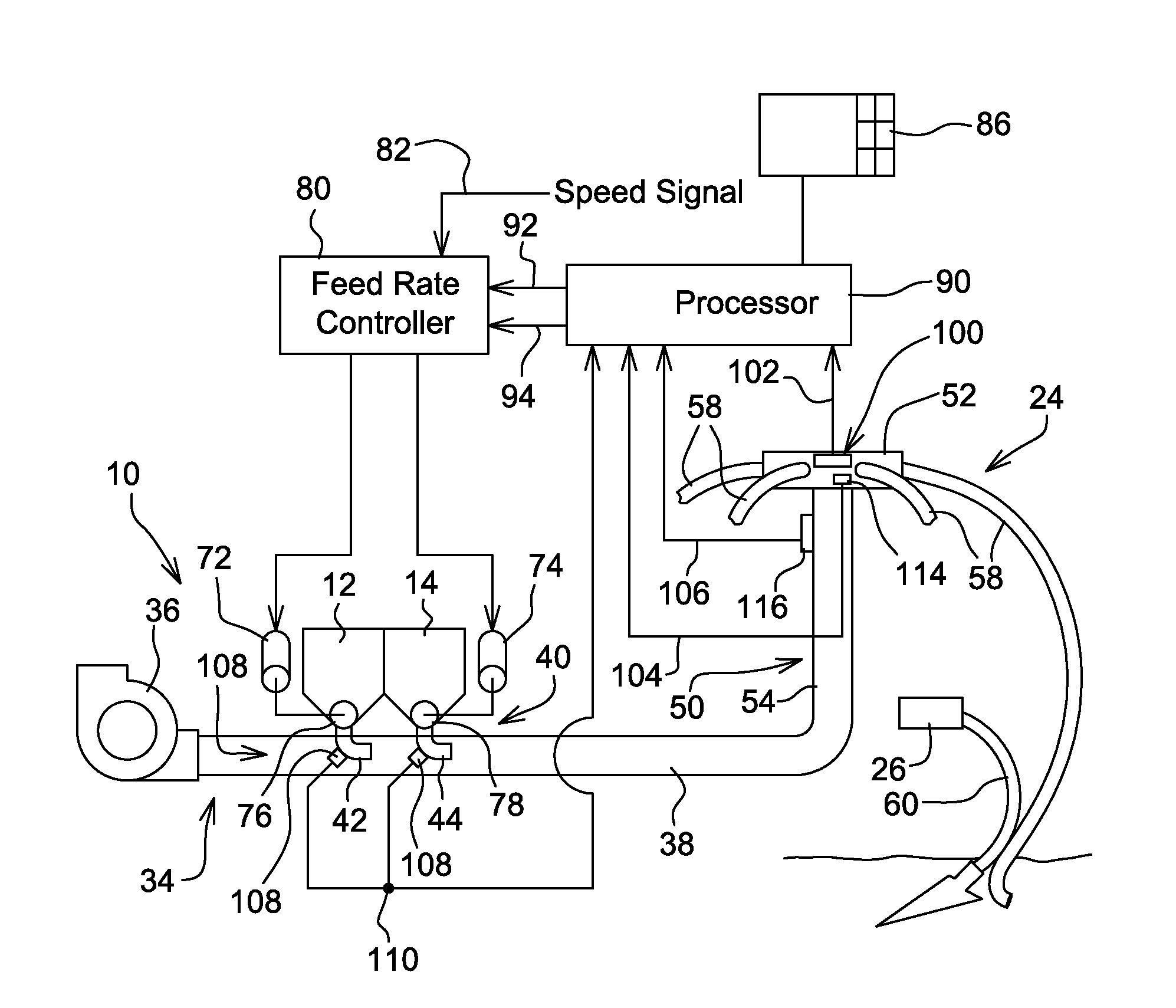
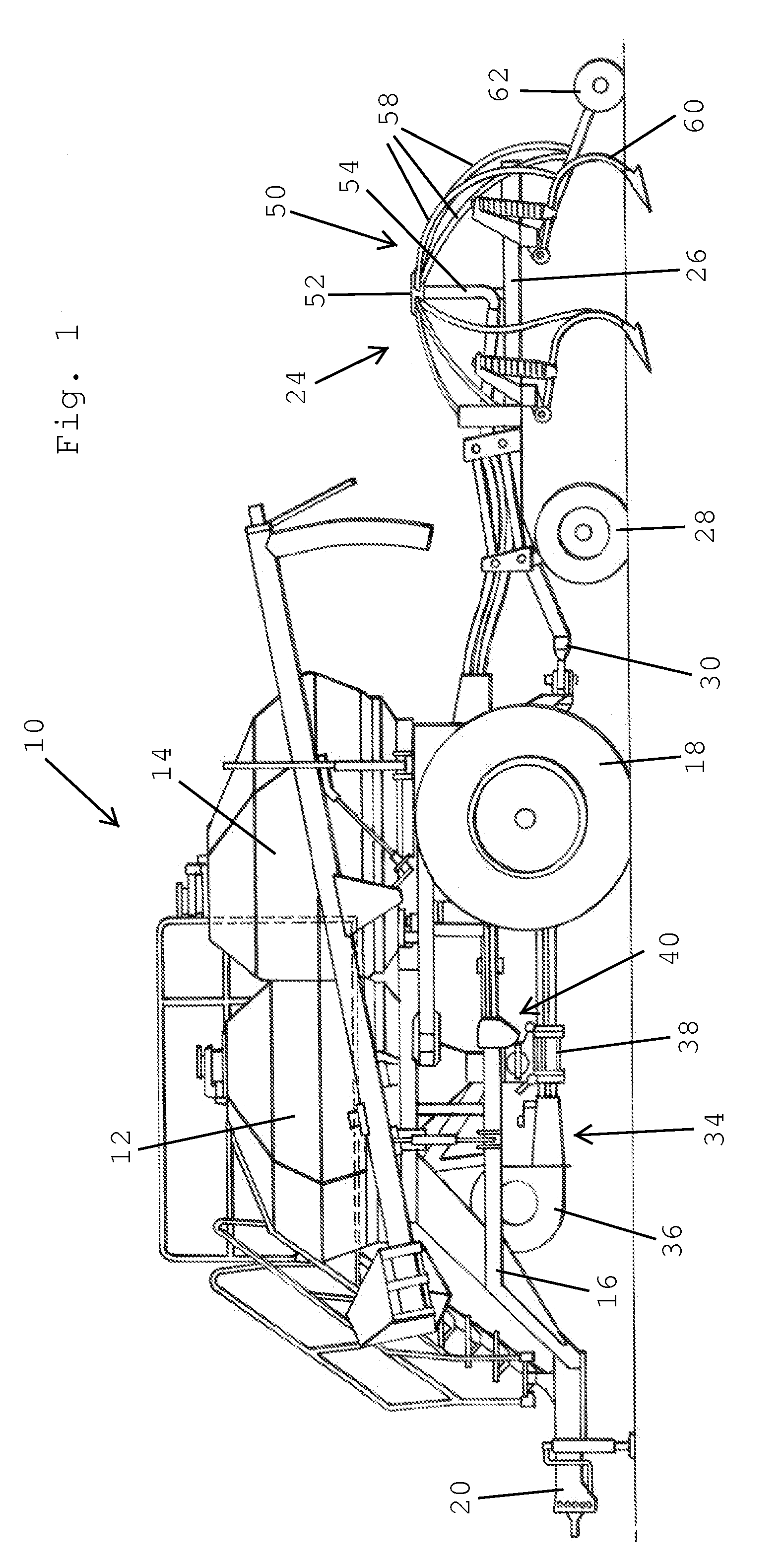
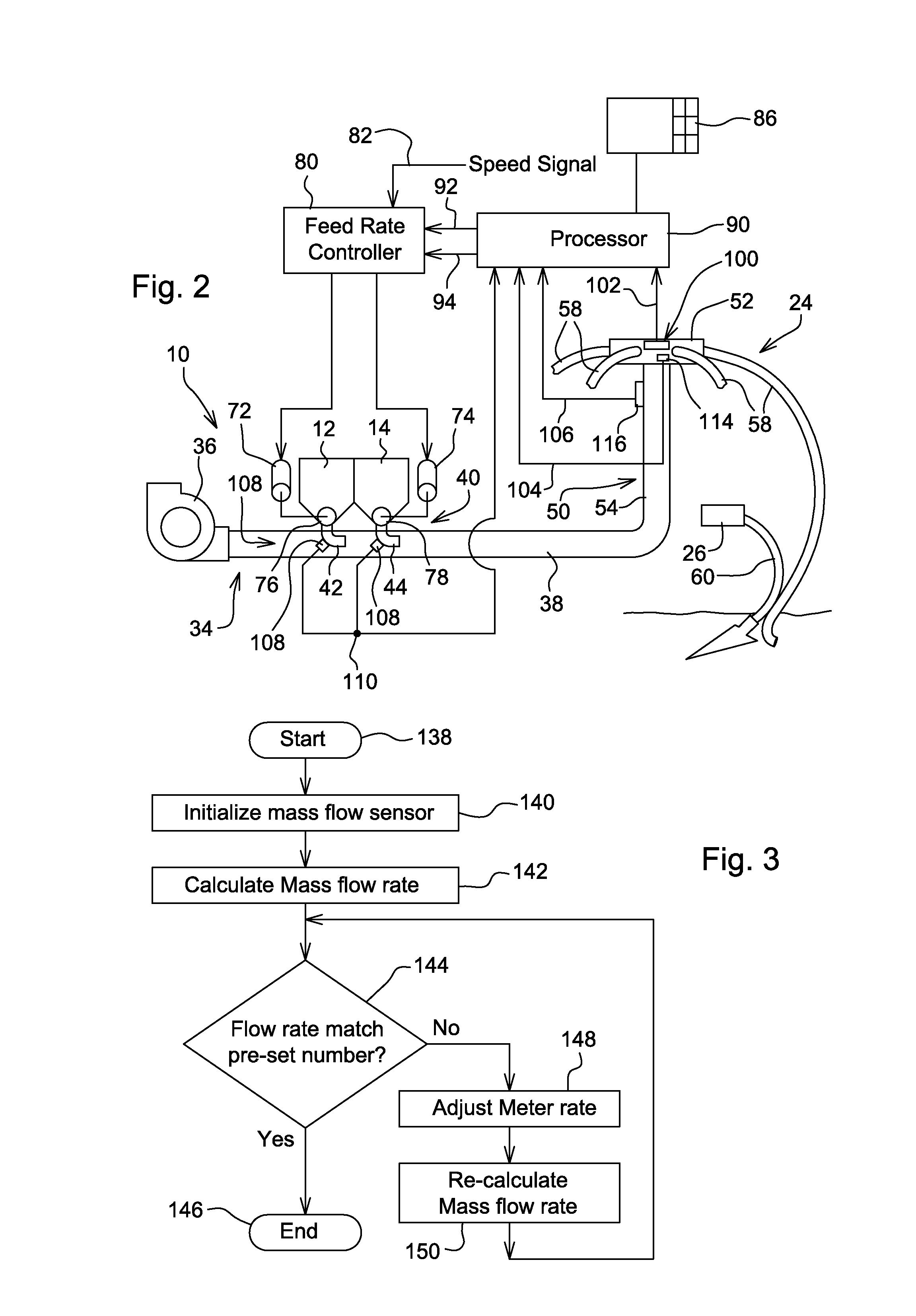
[0021]Referring to FIG. 1, therein is shown a seeding and fertilizing implement 10 including tanks 12 and 14 for containing materials to be distributed to the soil. The tanks 12 and 14 are mounted on a frame 16 supported by ground wheels 18 for forward movement over the ground by a towing vehicle (not shown) connected to a forward hitch 20. A ground-engaging implement 24 includes a frame 26 supported by ground wheels 28 and connected to the rear of the frame 16 by a hitch 30.

[0022]An air system 34 includes a fan 36 connected to the frame 16 and directing air rearwardly through material delivery conduit structure 38. Material metering structure 40 delivers the materials from the tanks 12 and 14 through venturi structure 42 and 44 into the material delivery conduit structure 38. The material is then carried rearwardly in the air stream to secondary distribution towers 50. Each tower 50 includes an uppermost distributing head 52 located at the uppermost end of a vertical distribution t...


PUM


Abstract

An impact sensor is located in a distribution tower which divides the seed and / or nutrient flow into individual rows, and a second sensor provides a compensation signal dependent upon one or more variables such as the velocity of the air in the conveying system, implement vibrations. As the seed / fertilizer bounces off of the impact sensor and flows into the individual row air streams, the impact sensor provides a force signal to a processor which calculates the total particulate mass flow rate from the force signal and the air velocity signal. To determine individual seed and fertilizer rates, a rate controller temporarily changes the metering rate of one of the materials, and the processor then calculates the desired information from the mass flow change and meter speed change. Another embodiment includes seed sensor structure at the meter output for achieving or confirming accuracy.

Description

FIELD OF THE INVENTION[0001]The present invention relates generally to air seeders and, more specifically, to mass flow sensors for such seeders.BACKGROUND OF THE INVENTION[0002]Air Seeding machines include a metering device which regulates that amount of seed and fertilizer that is dispensed into an air stream. The air stream conveys the seed and / or fertilizer to a secondary tower which divides the flow of materials into individual row air streams for delivery to furrows made in soil by a furrow opener. The current technology metering devices meter the seed or granular fertilizer on a volumetric basis. In order to achieve an acceptable degree of metering accuracy, the metering device must be calibrated in accordance with the density of the material being metered. The calibration procedure, which typically includes a manual weighing step, can be time consuming and, depending upon the skill level of the operator, can be inaccurate and result in reduced productivity. When more than on...

Claims


Application Information

Patent Timeline
Patent Type & Authority Patents(United States)
IPC IPC(8): G01F1/05G01F1/07G01F1/08G01F1/20
CPCA01C7/105A01C7/081A01C7/107Y02P60/00
Inventor LANDPHAIR, DONALD K.PHELAN, JAMES J.LIU, JAMES Z.
Owner DEERE & CO
Why Eureka
Try Eureka