Methods and apparatus for aligning print heads

a technology of inkjet printing and aligning apparatus, which is applied in the direction of typewriters, power drive mechanisms, coatings, etc., can solve the problems of affecting the accuracy of the system, the difficulty of accurately and precisely aligning inkjet ink or other materials on the substrate,

Inactive Publication Date: 2006-05-04
APPLIED MATERIALS INC
View PDF99 Cites 73 Cited by
  • Summary
  • Abstract
  • Description
  • Claims
  • Application Information

AI Technical Summary

Problems solved by technology

One problem with effective employment of inkjet printing is that it is difficult to inkjet ink or other material accurately and precisely on a substra

Method used


Image

  • Methods and apparatus for aligning print heads
  • Methods and apparatus for aligning print heads
  • Methods and apparatus for aligning print heads

Examples


Embodiment Construction

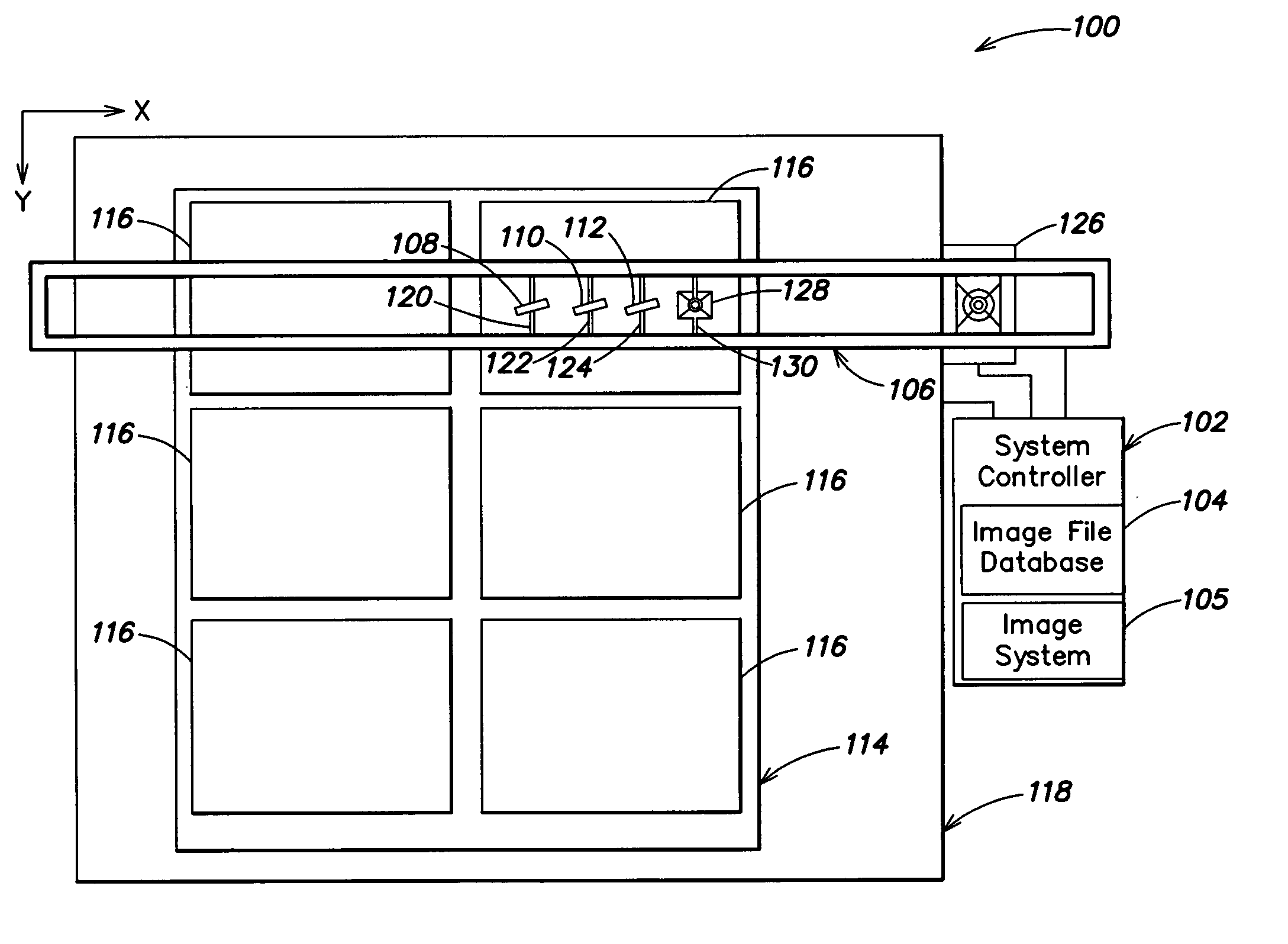
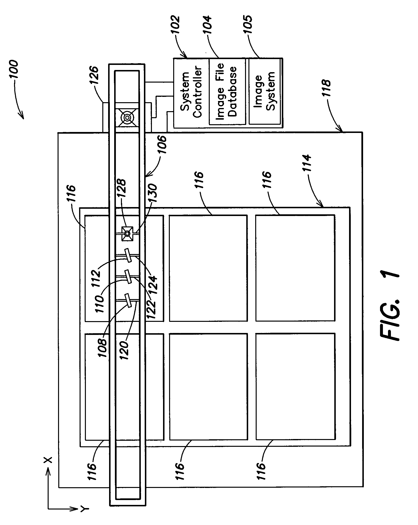
[0017] The present invention provides methods and apparatus to precisely calibrate a position and orientation control mechanism of a print head for an inkjet printing system. The precise calibration of a print head positioning control mechanism may be desirable because the nozzle to nozzle spacing of a print head may not match the display pixel pitch of a display object to be printed. Rotation of the print head along its center axis may allow each nozzle to be aligned with the center of a display pixel to be printed.

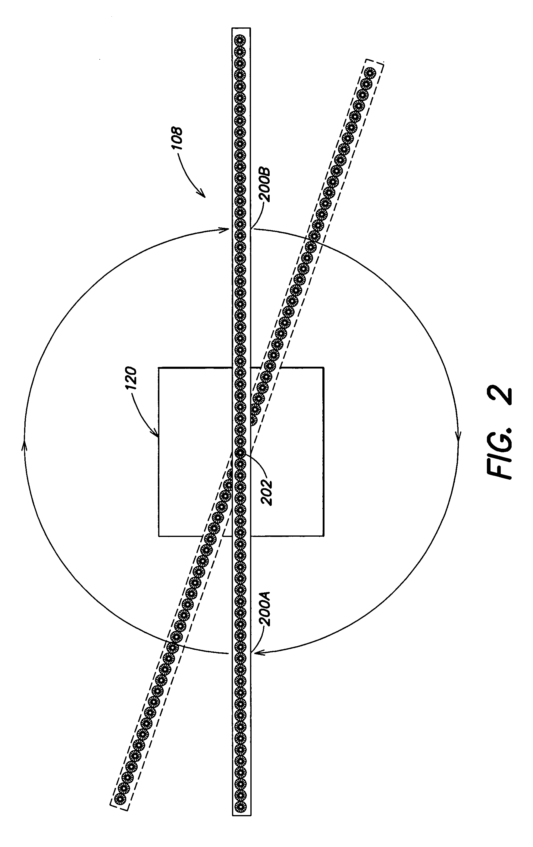
[0018] Through the use of an imaging system, a center point of the print head may be located. In one or more embodiments, this may be achieved by rotating the print head in a horizontal plane about the print head's center over a fixed camera of the imaging system. For example, the camera may be aimed upward and mounted to a stationary portion (e.g., a frame) of a stage used to move a substrate under the print head during printing. Other camera locations and / or orientati...


PUM


Abstract

In a first aspect, a system is provided. The system includes (1) a stage adapted to move a substrate relative to print heads during printing; (2) at least one print head suspended from a support above the stage and adapted to be moveable in a plane above the stage; (3) a controller operable to rotate the print head about a center of the print head; and (4) an imaging system adapted to capture an image of the print head and to determine a center point of the print head based upon images of the print head captured as the print head is rotated. Numerous other aspects are provided.

Description

[0001] The present application claims priority to commonly-assigned, co-pending U.S. Provisional Patent Application Ser. No. 60 / 625,550, filed Nov. 4, 2004 and entitled “APPARATUS AND METHODS FOR FORMING COLOR FILTERS IN A FLAT PANEL DISPLAY BY USING INKJETTING” which is hereby incorporated herein by reference in its entirety for all purposes. CROSS REFERENCE TO RELATED APPLICATIONS [0002] The present application is related to the following commonly-assigned, co-pending U.S. Patent Applications, each of which is hereby incorporated herein by reference in its entirety for all purposes: [0003] U.S. patent application Ser. No. ______, filed Dec. 22, 2004 and titled “APPARATUS AND METHODS FOR AN INKJET HEAD SUPPORT HAVING AN INKJET HEAD CAPABLE OF INDEPENDENT LATERAL MOVEMENT” (Attorney Docket No. 9521-1); and [0004] U.S. patent application Ser. No. ______, filed Dec. 22, 2004 and titled “METHODS AND APPARATUS FOR INKJET PRINTING” (Attorney Docket No. 9521-2). FIELD OF THE INVENTION [00...

Claims


Application Information

Patent Timeline
IPC IPC(8): B41J29/38
CPCB41J2/04505B41J2/04541B41J2/04581B41J2/04588B41J2/0459B41J2/04593B41J2/125B41J3/407B41J3/543B41J25/003B41J25/005B41J29/15B41J29/393B41J25/001B41J3/28
Inventor WHITE, JOHN M.SZE, FAN CHEUNGSHANG, QUANYUANKURITA, SHINICHIJI, HONGBINJOZWIAK, JANUSZHUANG, INCHENBEER, EMANUAL
Owner APPLIED MATERIALS INC
Why Eureka
Try Eureka