Imaging platform for nanoparticle detection applied to SPR biomolecular interaction analysis

a biomolecular interaction and nanoparticle technology, applied in the field of imaging objects, can solve the problems of limiting the use of spr analytical in the laboratory, limiting the throughput of commercial spr biosensors, and limiting the use of spr analytical methods, so as to increase the linearity of curves

Inactive Publication Date: 2006-06-06
CYTEK BIOSCI
View PDF46 Cites 73 Cited by
  • Summary
  • Abstract
  • Description
  • Claims
  • Application Information

AI Technical Summary

Benefits of technology

[0025]Corrections can be made to a nanoparticle response curve that exhibits a non-linear response. Specifically, larger nanoparticles may be used to increase the curve's linearity, and calibration corrections can be made for the non-linear response.

Problems solved by technology

However, to date, all such measurements have been performed primarily on bulk homogeneous suspensions of nanoparticles, due to the challenge of individually addressing and detecting these small objects.
However, the above mentioned prior art techniques are currently limited by throughput, mass transport diffusion, and depletion of small concentrations of analytes.
Commercial SPR biosensors are currently limited to four-channel detection.
This fact, and the relatively high degree of training necessary to operate these instruments and analyze the results, currently limit SPR analytical use in the laboratory.
However, most if not all of these approaches are directed toward optical configurations that can only detect a single angle or single wavelength intensity.
Therefore, changes in the association or dissociation of bio-molecules are detected as an intensity change, which has limited sensitivity and limited dynamic range compared to full spectral SPR data, where the entire angular or wavelength spectrum is measured, enabling a high precision measurement of the coupling angle or wavelength.
The prior art does not teach or suggest a complete solution to the problems discussed above.

Method used


Image

  • Imaging platform for nanoparticle detection applied to SPR biomolecular interaction analysis
  • Imaging platform for nanoparticle detection applied to SPR biomolecular interaction analysis
  • Imaging platform for nanoparticle detection applied to SPR biomolecular interaction analysis

Examples


Embodiment Construction

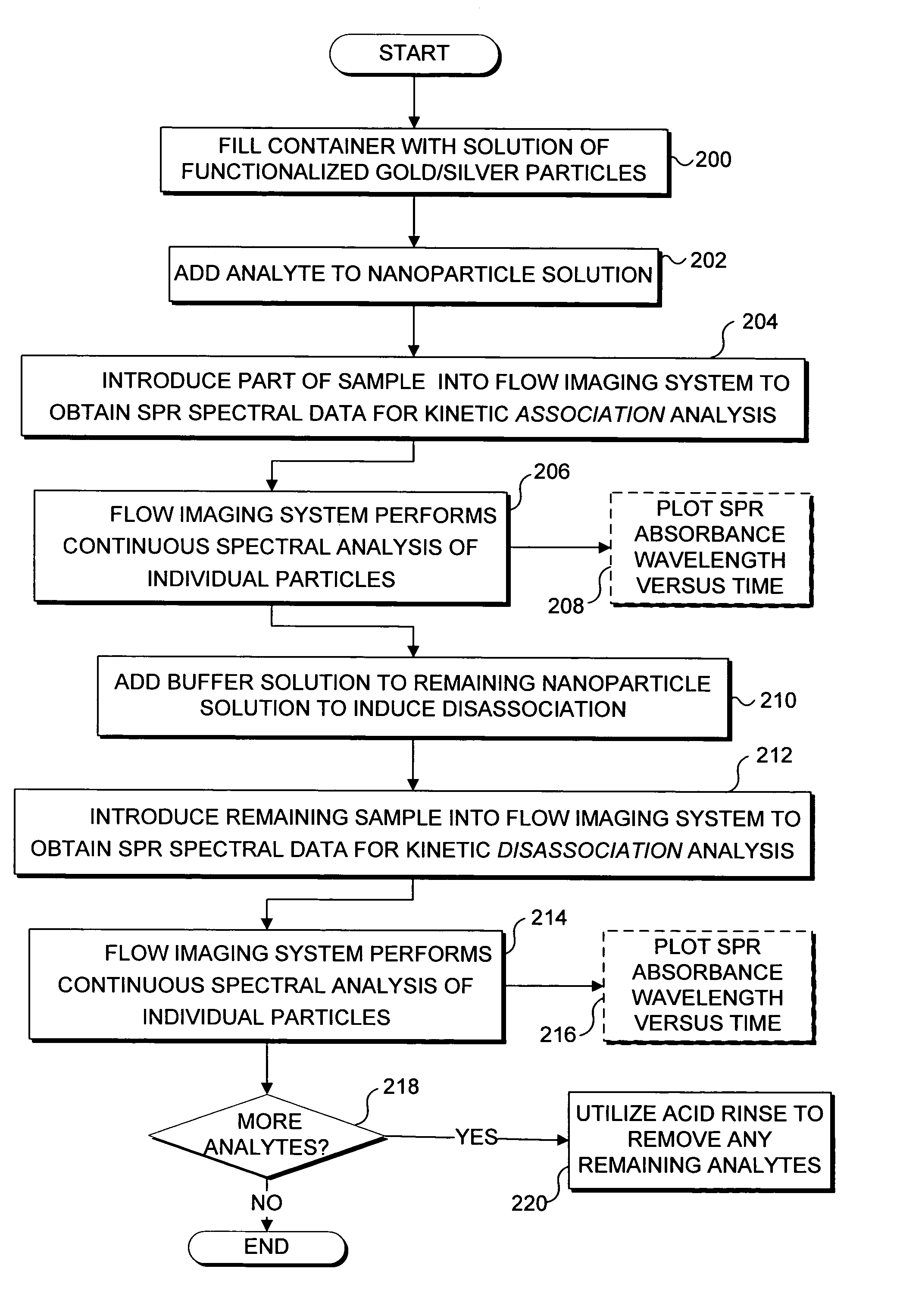
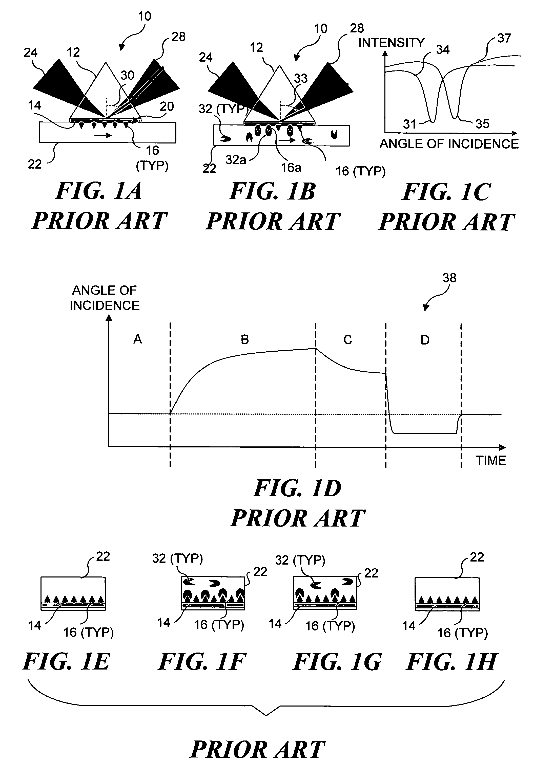
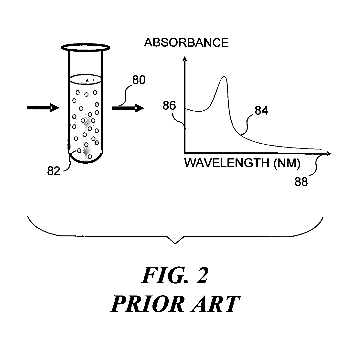
[0053]The present invention encompasses a method of using flow imaging systems that can combine the speed, sample handling, and cell sorting capabilities of flow cytometry with the imagery, sensitivity, and resolution of multiple forms of microscopy and full visible / near infrared spectral analysis to collect and analyze SPR spectra from objects entrained in a flow of fluid that emit an SPR spectra. Conventional methods of collecting and analyzing SPR spectra either employ a fixed sensor that emits SPR spectra as a solution of particles interacts with a fixed sensor, or emits a combined spectra from a bulk solution of particles that individually emit SPR spectra. The fixed sensor embodiment is widely used, but has a limited throughput. The spectra collected from the bulk solution does not enable spectra from individual particles to be discerned. In contrast, the present invention enables SPR spectra from individual particles to be collected with a much greater throughput than achieva...


PUM

PropertyMeasurementUnit
diameteraaaaaaaaaa
diameteraaaaaaaaaa
pixel sizeaaaaaaaaaa

Abstract

A flow imaging system is used to implement surface plasmon resonance (SPR) detection to study bio-molecular interactions. The flow imaging system is used to capture SPR absorption spectra of large numbers of objects, where each object includes both a metal film capable of exhibiting SPR, and detecting molecules. Analyte molecules are added to a solution of such objects, and the result is introduced into the flow imaging system which collects full SPR spectral data from individual objects. The objects can be nanoparticles or larger particles that support metal island films. The SPR spectral data can be used to determine specificity, kinetics, affinity, and concentration with respect to the interactions between the detecting molecules and the analyte molecules.

Description

RELATED APPLICATIONS[0001]This application is based on a prior copending provisional application, Ser. No. 60 / 451,346, filed on Feb. 27, 2003, the benefit of the filing date of which is hereby claimed under 35 U.S.C. § 119(e). This application is also a continuation-in-part application of a copending patent application Ser. No. 10 / 628,662, filed on Jul. 28, 2003, now U.S. Pat. No. 6,975,400, which itself is a continuation-in-part application of a copending patent application Ser. No. 09 / 976,257, filed on Oct. 12, 2001, now U.S. Pat. No. 6,608,682 (issued Aug. 19, 2003), which is a continuation-in-part application of a copending patent application Ser. No. 09 / 820,434, filed on Mar. 29, 2001, now U.S. Pat. No. 6,473,176 (issued Oct. 29, 2002), which is a continuation-in-part application of patent application Ser. No. 09 / 538,604, filed on Mar. 29, 2000, now U.S. Pat. No. 6,211,955 (issued Apr. 3, 2001), which itself is a continuation-in-part application of patent application Ser. No. 0...

Claims


Application Information

Patent Timeline
Patent Type & Authority Patents(United States)
IPC IPC(8): G01N21/55G01J3/28G01N15/02G01N15/10G01N15/14G01N21/05G01N21/25G01N21/64G01N21/65G01N21/75G01N21/85G02B7/28G02B27/14
CPCB82Y15/00G02B27/1013G01J3/2803G01J3/2823G01N15/147G01N21/554G01N21/6428G01N21/648G01N21/658G01N21/85G01N33/54346G02B7/28B82Y20/00G01N15/1434G01N2015/0294G01N2015/1006G01N2015/1472G01N2015/1486G01N2021/052G01N2021/058G01N2021/258
Inventor JORGENSON, RALPH C.BASIJI, DAVID A.ORTYN, WILLIAM E.
Owner CYTEK BIOSCI
Why Eureka
Try Eureka