Pump impeller and chopper plate for a centrifugal pump

a centrifugal pump and impeller technology, applied in the field of centrifugal pumps, can solve the problems of no structure about which stringy solids can adhere or wrap to cause a dead zone in the center of the impeller pump, and achieve the effect of improving flow efficiency

Inactive Publication Date: 2005-03-03
ENVIROTECH PUMPSYSTEMS INC
View PDF16 Cites 10 Cited by
  • Summary
  • Abstract
  • Description
  • Claims
  • Application Information

AI Technical Summary

Benefits of technology

[0010] In accordance with the present invention, an impeller and associated chopper plate having a cutter bar are designed for use in a centrifugal pump of the chopper type to provide cutting action across the center axis of the pump at the impeller eye to avoid entrapment or clogging of solid material in a central zone as experienced in conventional chopper pumps. Further in accordance with the present invention, the impeller is designed to provide flow of fluid through the eye of the impeller to improve flow efficiencies.
[0011] A chopper pump of the present invention is structured with a chopper plate that is configured with a cutter bar that is positioned to interact with the impeller vanes of the pump to effect a chopping and / or cutting action on solids entrained in fluid entering the pump. More importantly, the chopper plate is structured with at least one cutter bar that extends across the radius of the opening of the chopper plate, thereby spanning a substantial portion of the radius of the pump impeller to improve chopping and cutting efficiencies.
[0014] Because the cutter bar of the chopper plate extends along the radius of the opening of the chopper plate and spans a substantial portion of the radius of the impeller, the cutter bar is stronger and more durable than cutter bars of prior art chopper pumps. That is, in some known chopper pumps that employ cutter bars on a chopper or intake plate, the cutter bars extend from a position near the periphery of the chopper plate toward the center of the pump near the impeller eye, but end short of the center near the eye of the impeller. Consequently, the cutter bars can become damaged or broken off when encountering very hard solids.
[0015] The chopper pump of the present invention further includes an impeller that is configured to interact with the chopper plate and chopper bar to efficiently cut and chop solids entrained in the fluid. Specifically, the impeller is of an open eye configuration which eliminates any centrally or axially extending element that might become clogged with solid (usually stringy) debris, thereby causing a dead zone in the center of the impeller. Further, the open eye configuration of the impeller enables solids and fluid to flow through the eye of the impeller, thereby improving pump efficiencies as compared with conventional chopper pumps. The impeller of the present invention may be shroudless or have a shroud positioned on the drive side of the impeller.

Problems solved by technology

Furthermore, because the “hubless” arrangement eliminates the conventional obstructive elements at the center of the impeller or chopper plate on the suction side, there is no structure about which stringy solids can adhere or wrap to cause a dead zone in the center of the impeller pump.

Method used


Image

  • Pump impeller and chopper plate for a centrifugal pump
  • Pump impeller and chopper plate for a centrifugal pump
  • Pump impeller and chopper plate for a centrifugal pump

Examples


Embodiment Construction

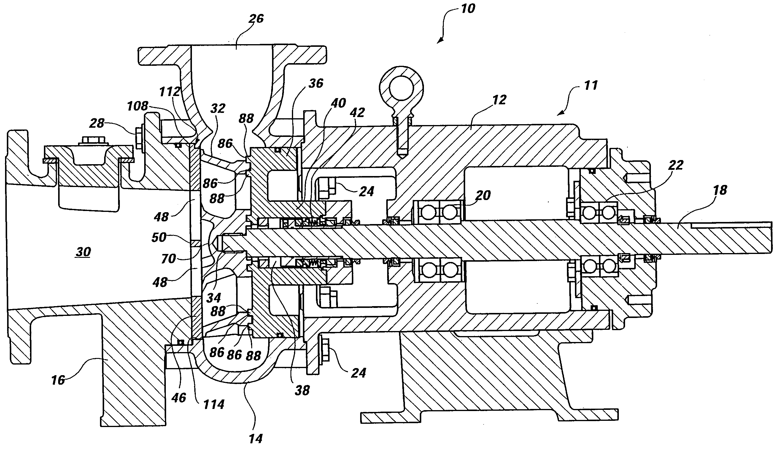
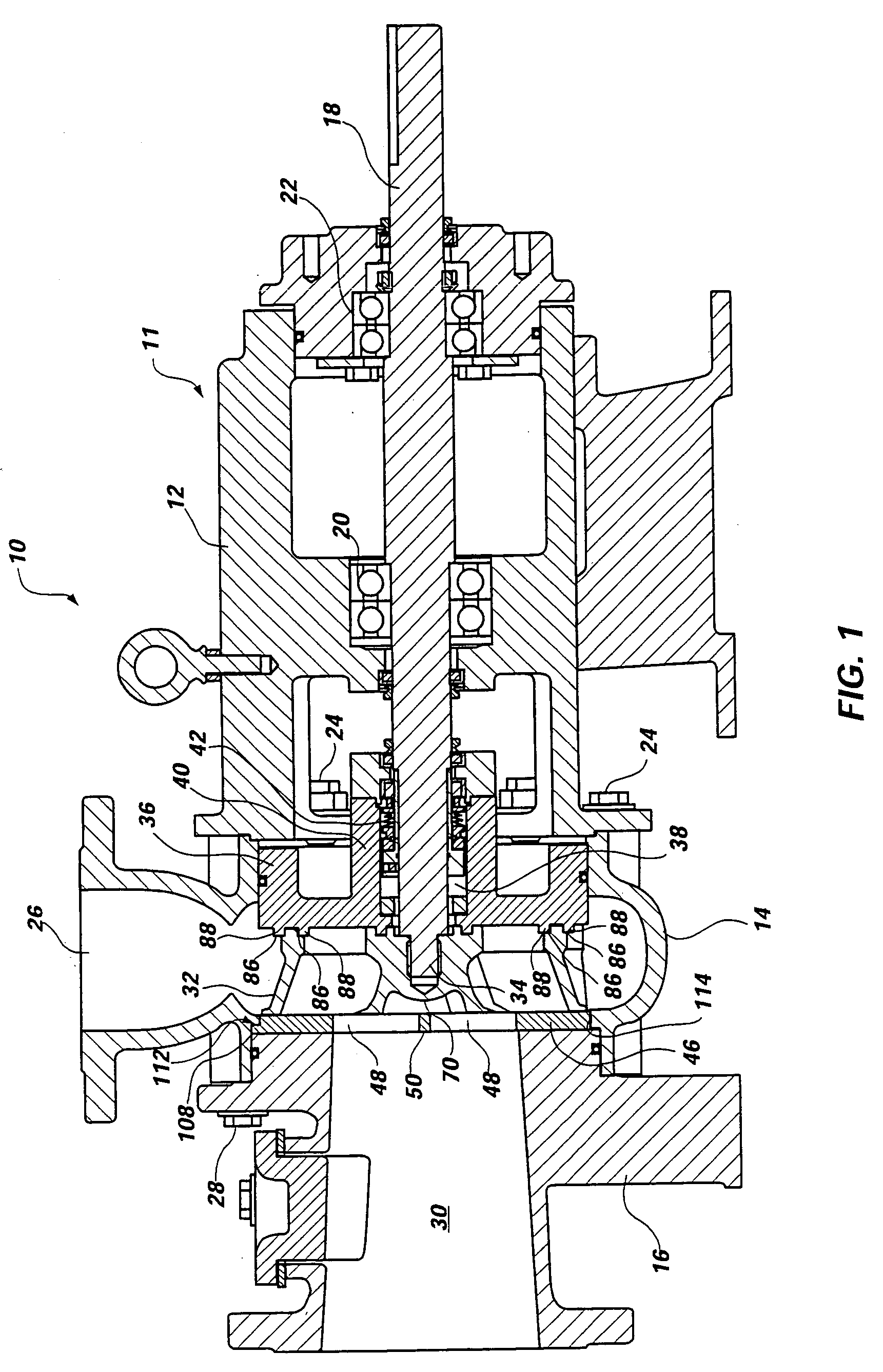
[0035] In accordance with the present invention, a centrifugal pump 10 of the chopper type is shown in FIG. 1. The chopper pump 10 generally comprises a pump casing 11 that houses the inner working elements of the pump 10 and may vary in configuration and structure. However, by way of example, the pump casing 10 illustrated in FIG. 1 includes a drive casing 12, a volute casing 14 and a suction casing 16. The drive casing 12 generally houses a drive shaft 18, which is supported by bearings 20, 22. The volute casing 14, which is secured to the drive casing by bolts 24, is structured with an outlet 26 for egress of processed fluid and solids from the pump 10. The suction casing 16, which is secured to the volute casing 14 by bolts 28, provides an inlet 30 through which fluid and solids are directed for processing by the pump 10.

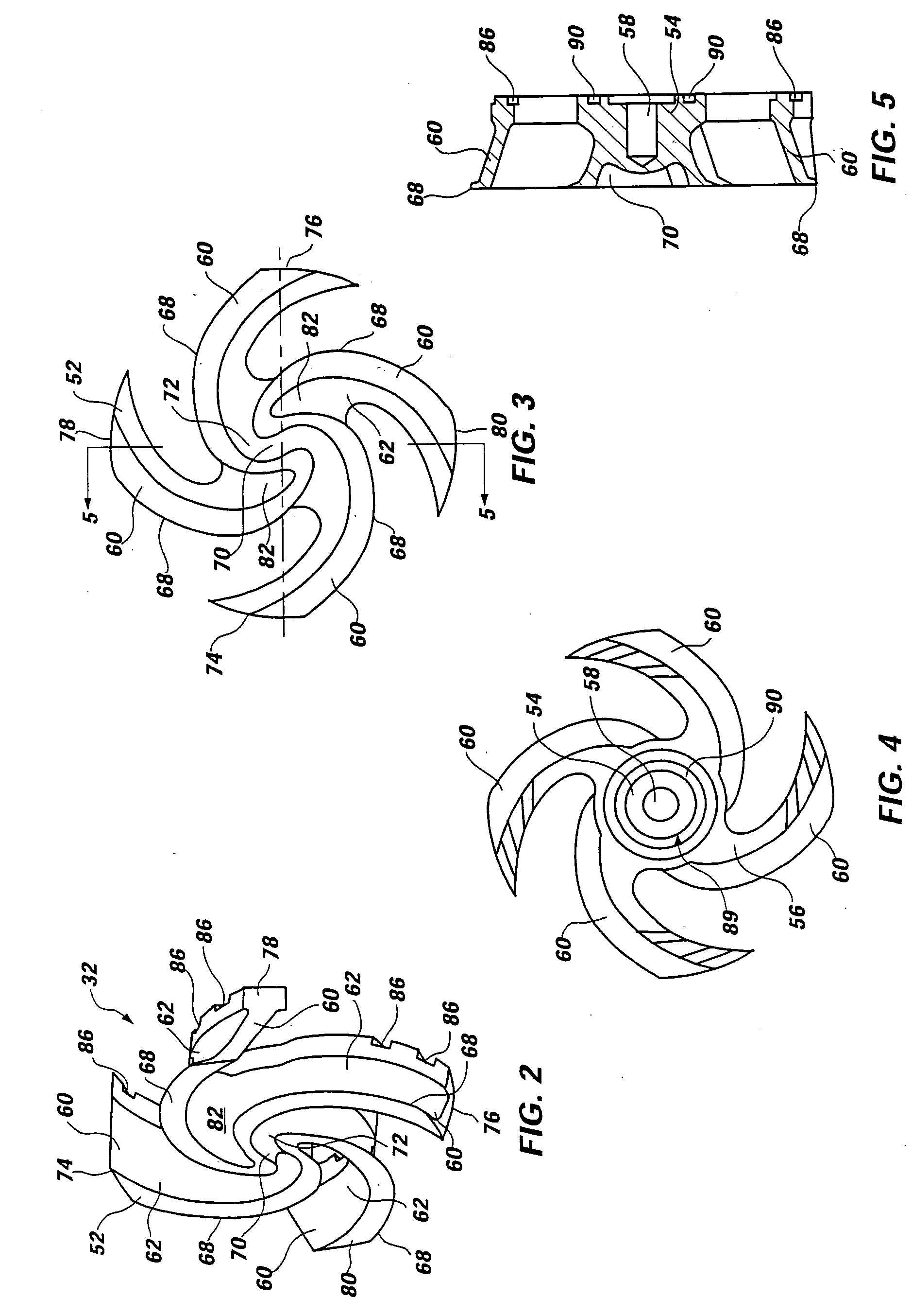
[0036] The impeller 32 of the present invention is shown positioned within the volute casing 14 and is secured to the terminal end 34 of the drive shaft 18. In...


PUM


Abstract

A centrifugal pump of the chopper type is disclosed which is structured with a chopper plate and impeller that are configured with an open eye or “hubless” arrangement such that processing of solids through the pump does not result in clogging of solids at or near the center of the impeller, thereby producing a dead zone. Because the configuration of the chopper pump of the present invention avoids the development of a central dead zone or clogging of solids, and provides for flow of solids and fluid through the eye of the impeller, pump efficiencies are markedly improved.

Description

CROSS-REFERENCE TO RELATED APPLICATION [0001] This application is a non-provisional application claiming priority to provisional patent application Ser. No. 60 / 482,977 filed Jun. 27, 2003.BACKGROUND OF THE INVENTION [0002] 1. Field of the Invention [0003] This invention relates to centrifugal pumps of the type commonly known as chopper pumps, which are configured to process solid waste materials such as medical waste, municipal waste and food-processing waste. Specifically, this invention relates to an impeller and chopper plate having a cutter bar structured for use in a chopper pump. [0004] 2. Description of Related Art [0005] Various industries involve or require the processing of solid waste material into a form that can be disposed of in a suitable manner. Certain solid wastes containing or comprising, for example, plastics, metals, animal byproducts and other hard or stringy materials present a particular challenge to processing the material into a disposable form. Therefore, ...

Claims


Application Information

Patent Timeline
Patent Type & Authority Applications(United States)
IPC IPC(8): F04D7/04F04D29/22
CPCF04D29/2288F04D7/045
Inventor DOERING, BRANDON R.HARMON, JAMES C.SHAW, JAMES G.
Owner ENVIROTECH PUMPSYSTEMS INC
Why Eureka
Try Eureka