Backlight module

A backlight module and light guide plate technology, applied in optics, nonlinear optics, instruments, etc., can solve problems such as light leakage from the light guide plate

Inactive Publication Date: 2007-07-18
CHUNGHWA PICTURE TUBES LTD
View PDF0 Cites 11 Cited by
  • Summary
  • Abstract
  • Description
  • Claims
  • Application Information

AI Technical Summary

Problems solved by technology

[0003] In order to solve the problem of light leakage at the ear of the light guide plate, an embodiment of the present invention provides a backlight module, which uses columns to ensure sufficient contact area with the light guide plate, so as to prevent light leakage

Method used


Image

  • Backlight module
  • Backlight module
  • Backlight module

Examples


Embodiment Construction

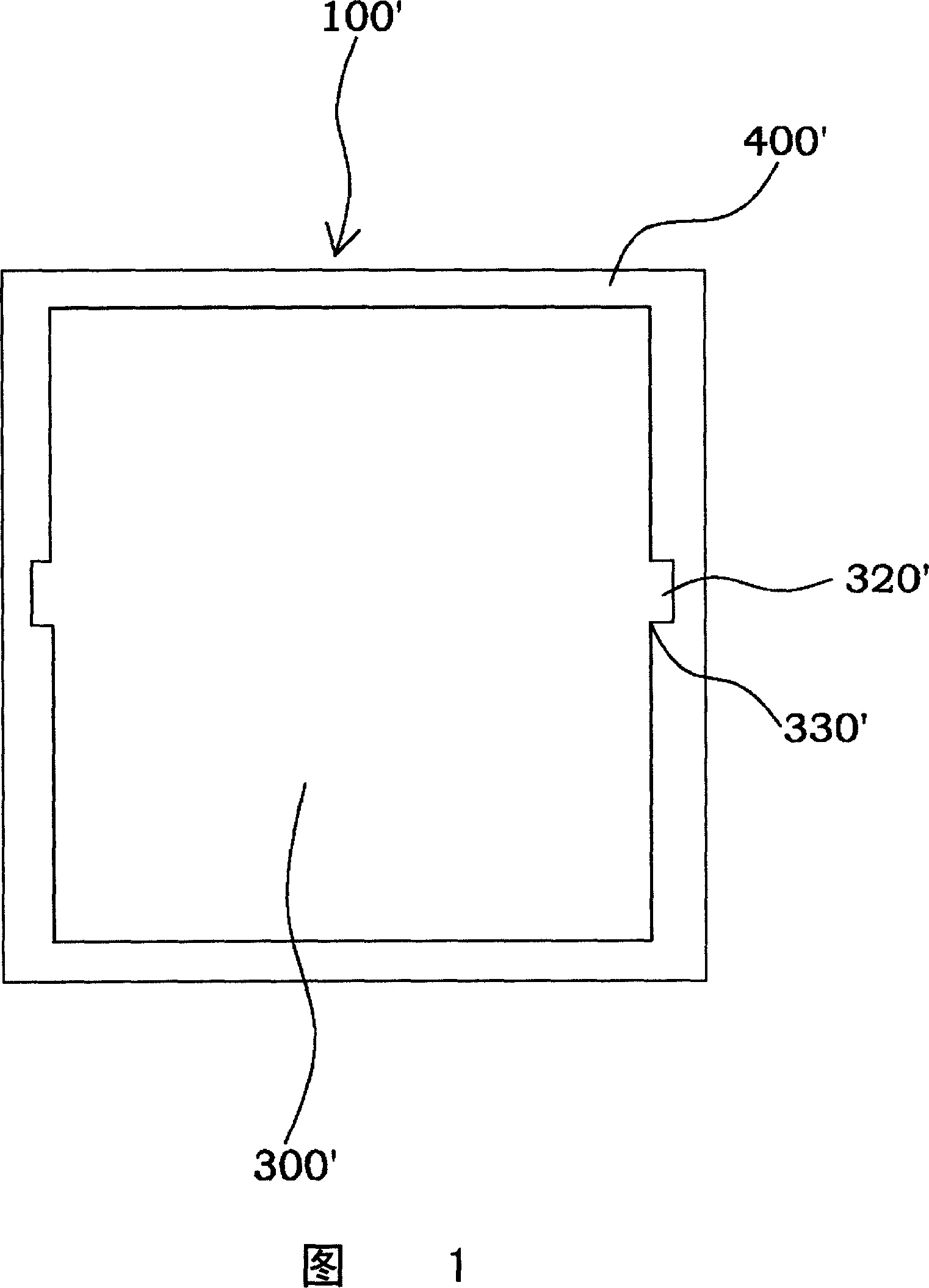
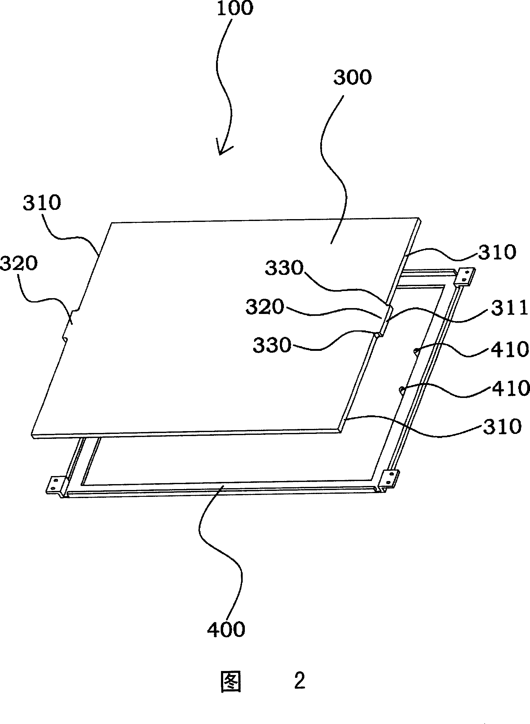
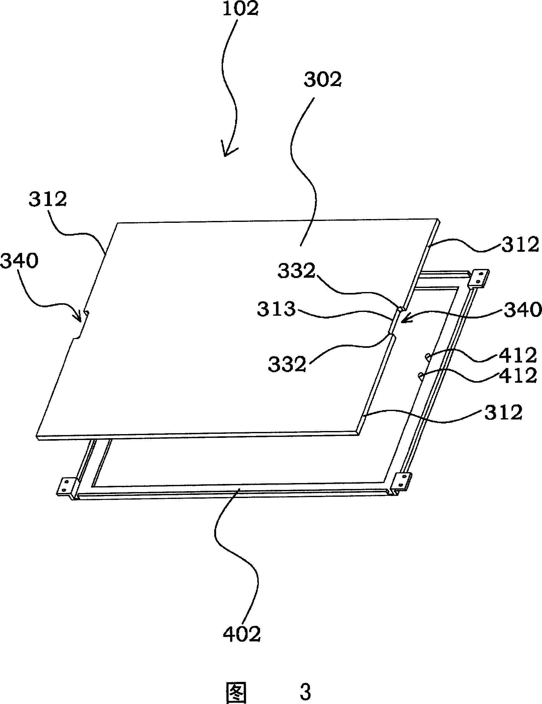
[0011] Please refer to FIG. 2 . FIG. 2 is a perspective view of a backlight module according to an embodiment of the present invention. In this embodiment, the backlight module 100 includes a light guide plate 300 and a corresponding outer frame 400 . Wherein, the light guide plate 300 includes a first peripheral edge 310 and a second peripheral edge 311, and the connection between the first peripheral edge 310 and the second peripheral edge 311 forms a guide angle 330, such as an arc-shaped guide angle. In one embodiment, the second The two peripheral edges 311 and the chamfer 330 define a protrusion 320 protruding from the first peripheral edge 310 . And in one embodiment, the protrusion 320 is located on the non-light-incident side of the light guide plate, so that the optical image is minimal. Next, an outer frame 400, such as a back plate, surrounds at least the first peripheral edge 310 and the second peripheral edge 311 of the light guide plate 300, and includes at lea...


PUM


Abstract

A backlight module consists of a light guiding plate with at least a lug or at least a notch and an external frame with at least a vertical column. It is featured as enabling to check lug or notch on light guiding plate with vertical column on external frame to each other when light guiding plate is combined with external frame.

Description

【Technical field】 [0001] The invention relates to a backlight module, in particular to a light guide plate positioning structure of the backlight module. 【Background technique】 [0002] With the advancement of technology, liquid crystal displays are rapidly expanding due to their features such as thinness, lightness, and power saving. However, since liquid crystal displays are non-self-luminous display devices, the display function needs to be generated through a backlight module. Among them, the positioning method of the light guide plate generally adopts a rubber frame or a baffle formed by punching the back plate. Fixing the light guide plate with a plastic frame has the advantage that the shape can be modified arbitrarily according to the mold; the disadvantage is that the assembly of the light guide plate requires reverse assembly, but the reverse assembly takes a long time and the yield rate is poor, which is not the mainstream trend in the general market. Please refe...

Claims


Application Information

Patent Timeline
Patent Type & Authority Applications(China)
IPC IPC(8): G02F1/1335G02F1/1333
Inventor 张庆龙
Owner CHUNGHWA PICTURE TUBES LTD
Why Eureka
Try Eureka