Method for implementing long jumping dynamic patch in embedded system

A technology of embedded system and implementation method, which is applied in the direction of instruments, electrical digital data processing, program control devices, etc.

Inactive Publication Date: 2007-07-25
ZTE CORP
View PDF0 Cites 41 Cited by
  • Summary
  • Abstract
  • Description
  • Claims
  • Application Information

AI Technical Summary

Problems solved by technology

[0014] For the dynamic patch upgrade of embedded system software, the solution that directly uses the long j

Method used


Image

  • Method for implementing long jumping dynamic patch in embedded system
  • Method for implementing long jumping dynamic patch in embedded system
  • Method for implementing long jumping dynamic patch in embedded system

Examples


Embodiment Construction

[0034] The present invention will be described in detail below in conjunction with the accompanying drawings.

[0035] The following is a specific example of the practical application of the present invention, which is a specific application under the PowerPC processor.

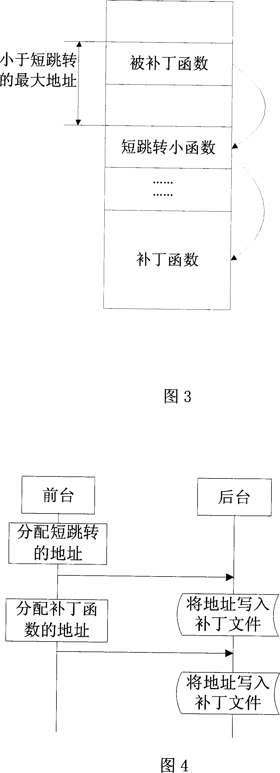
[0036] Referring to FIG. 3, FIG. 3 shows a schematic diagram of the complete process of completing the dynamic patch long jump based on the PowerPC processor in this example. To achieve the purpose of dynamic patch long jump based on PowerPC processor, this example needs the following steps:

[0037] (1) Step 1: After the system finds an error in the program, when generating the patch file according to the patch source file (. A small function) and the size of the patch function are allocated in the planned memory (satisfying that the small function area and the patched function area are within the address space of the short jump address range (16M)). And write its address into the patch file by the backgro...


PUM


Abstract

A method for realizing dynamic patch long slip of embedded system includes distributing internal memory for patch small function region and patch function region, writing address of patch small function and address of patch function into patch file, preparing relevant short skip command for patched function and relevant long skip command for small function when patch function is loaded to internal memory, realizing long skip of dynamic patch upgrading by skipping short skip to small function then to patch function when patch is activated.

Description

technical field [0001] The invention relates to a method for time-length jump in software dynamic patch upgrade, in particular to a method for realizing long-time jump when the relative addresses of the patch function and the patched function exceed the short jump address range. Background technique [0002] A software patch is a term in computer software systems and software engineering. It is generally an independent software unit released to modify certain errors in system software. The software dynamic patch upgrade technology is to complete the repair of system errors without affecting the normal operation of the system, that is, in the process of software operation, replace the old module with the patch module in real time, without interrupting the execution sequence of the original program . [0003] In the embedded field, the existing dynamic patch upgrade technology generally adopts a technical solution as shown in FIG. 1 . [0004] Wherein, the foreground is a ta...

Claims


Application Information

Patent Timeline
IPC IPC(8): G06F9/44G06F11/00
Inventor 王泽民徐立峰张华强
Owner ZTE CORP
Why Eureka
Try Eureka