Re-roating method

A routing and router technology, applied in the field of rerouting technology, can solve problems such as load increase, and achieve the effects of short switching time, short adjustment time, and easy deployment of large-scale multicast services.

Inactive Publication Date: 2007-07-25
HUAWEI TECH CO LTD
View PDF0 Cites 21 Cited by
  • Summary
  • Abstract
  • Description
  • Claims
  • Application Information

AI Technical Summary

Problems solved by technology

This will lead to a sudden and sharp increase in the load of a large number of LSR nodes, and even the CPU utilization rate reaches 100% for a long time.

Method used


Image

  • Re-roating method
  • Re-roating method
  • Re-roating method

Examples


Embodiment Construction
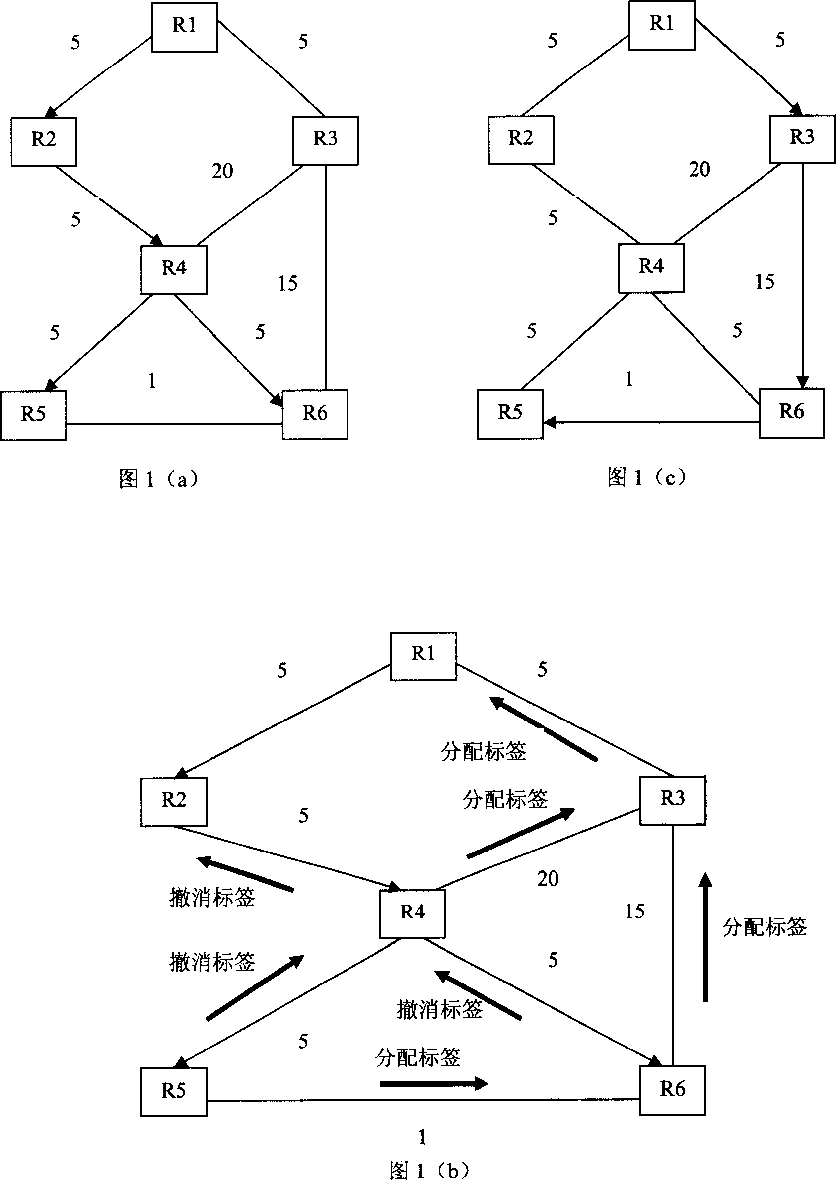
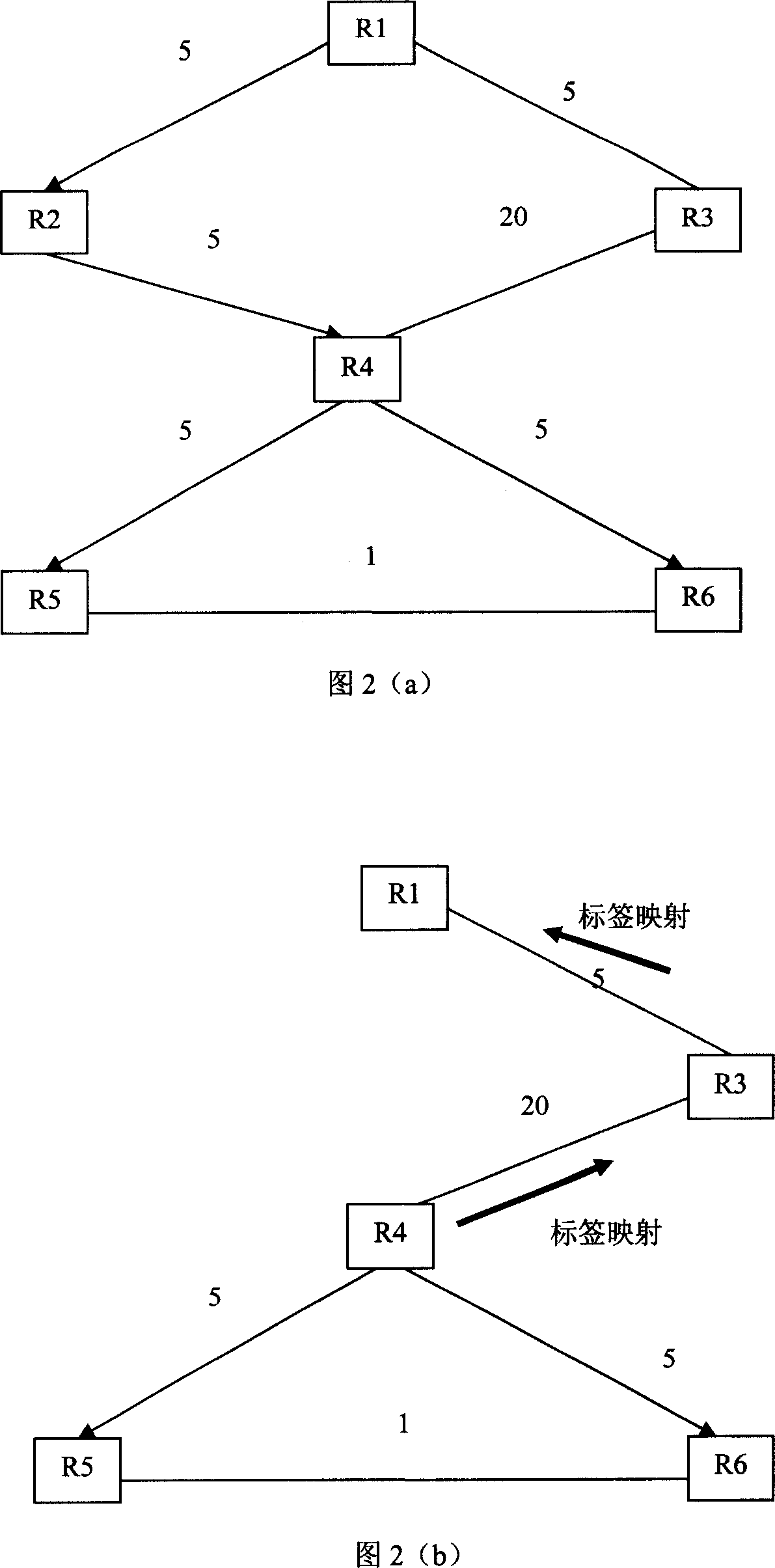
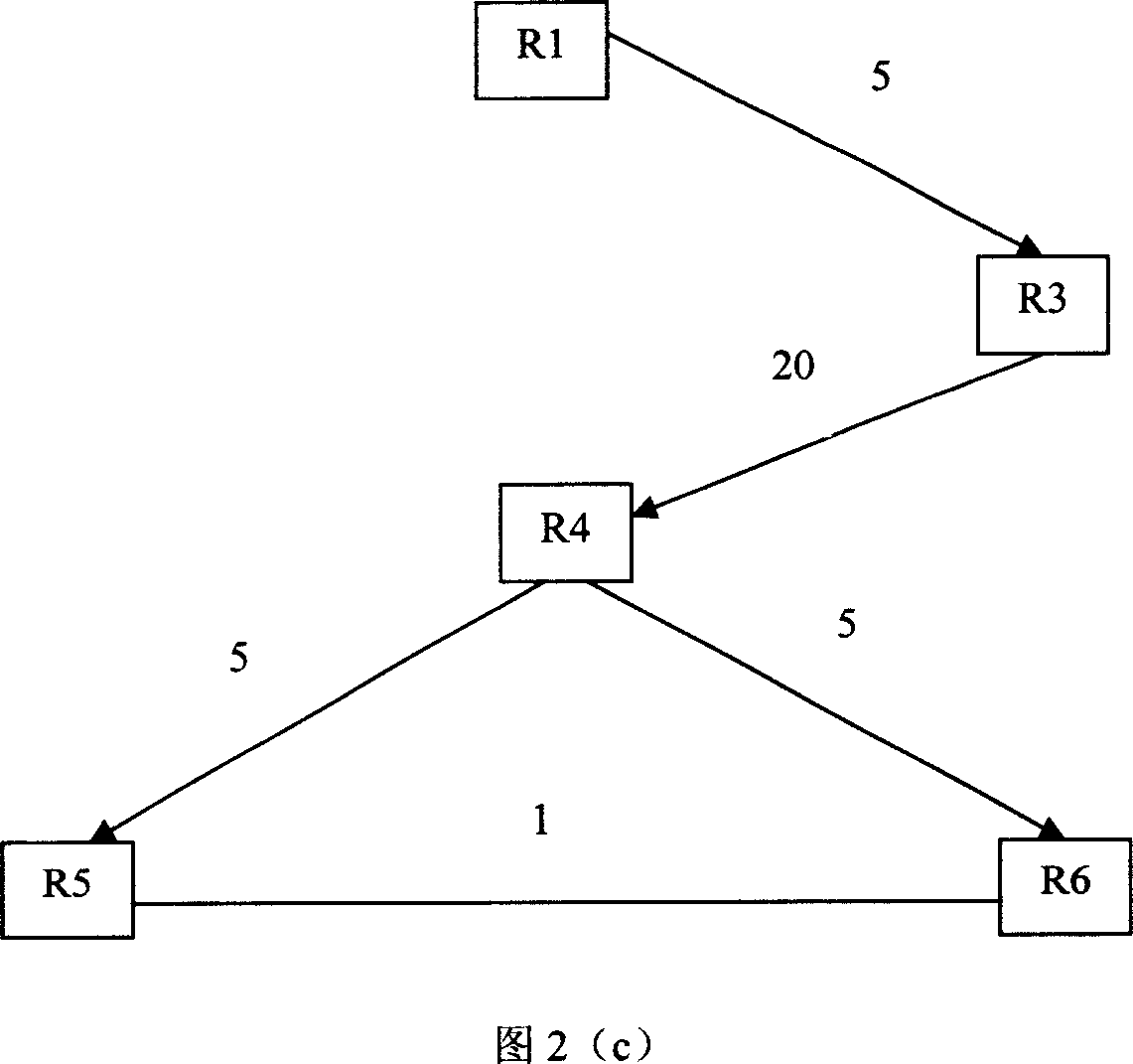
[0047] The core idea of ​​the rerouting method of the present invention is: when a network link or a router fails in a network switching path and causes a route change, by establishing a link between the failed router or the adjacent downstream router of the failed link and the source router, the The exchange path from the source router to the destination router is repaired, while the downstream routers of the router that re-establishes the link remain unchanged and are not adjusted. At the same time, the present invention further detects whether the repaired switching path or the switching path formed by routing changes due to other reasons is the shortest path, and if not, adjusts it to the shortest path. However, in the prior art, when a local route changes, all adjacent or non-adjacent routers located downstream of the changed routing part must be adjusted accordingly in order to re-establish the route as the routing information is transmitted across the entire network. , ...


PUM


Abstract

The method features the following points: when a failure link or a failure router appears in the network exchanging path, the downstream router adjacent the failure router or the failure link re-establish the exchange path; meanwhile, the source router sends the path detection message to decide if the path between the source router and the destination route is the shortest path; if not, the destination route sends the path modification message to re-establish a shortest path.

Description

technical field [0001] The invention relates to the communication field, and particularly discloses a rerouting technology. Background technique [0002] Multi-Protocol Label Switching (MPLS) is a method that introduces IP into communication networks such as Asynchronous Transfer Mode (ATM) or Frame Relay (Frame Relay), and uses labels to guide high-speed and efficient data transmission. technology. The application field of MPLS is constantly expanding. With the continuous development of the Internet, the use of IP routers with MPLS functions and ATM switches with MPLS functions to build future broadband integrated service communication networks has become a hot spot in the industry. The value of MPLS is that it can introduce a connection-oriented mechanism in a connectionless network, and its advantage is to reduce the complexity of the network and be compatible with various existing network technologies. At the same time, MPLS comprehensively utilizes the switching techn...

Claims


Application Information

Patent Timeline
Patent Type & Authority Applications(China)
IPC IPC(8): H04L12/56
CPCH04L45/28H04L69/40H04L45/26H04L45/50H04L45/00
Inventor 李贺军
Owner HUAWEI TECH CO LTD
Why Eureka
Try Eureka