Plasma processing apparatus

A plasma and processing device technology, which is applied in the field of plasma processing devices, can solve the problems of difficult sputtering etching of generated reactants, high difficulty, etc.

Inactive Publication Date: 2007-07-25
MITSUBISHI HEAVY IND LTD
View PDF0 Cites 2 Cited by
  • Summary
  • Abstract
  • Description
  • Claims
  • Application Information

AI Technical Summary

Problems solved by technology

However, in the conventional plasma processing device 10 described above, it is extremely difficult to sputter etch the generated reactants in a uniform amount, and the larger the diameter of the substrate 1, the higher the difficulty.

Method used


Image

  • Plasma processing apparatus
  • Plasma processing apparatus
  • Plasma processing apparatus

Examples


no. 1 Embodiment approach

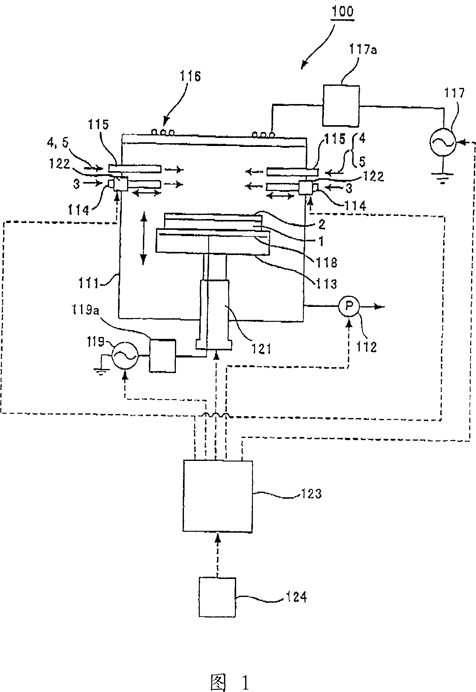
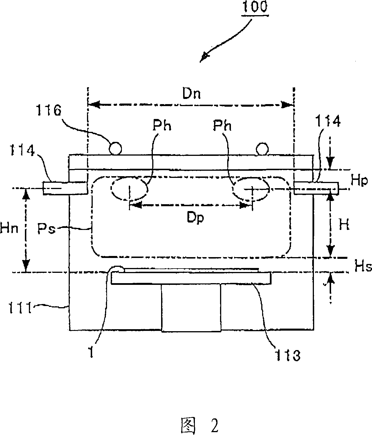
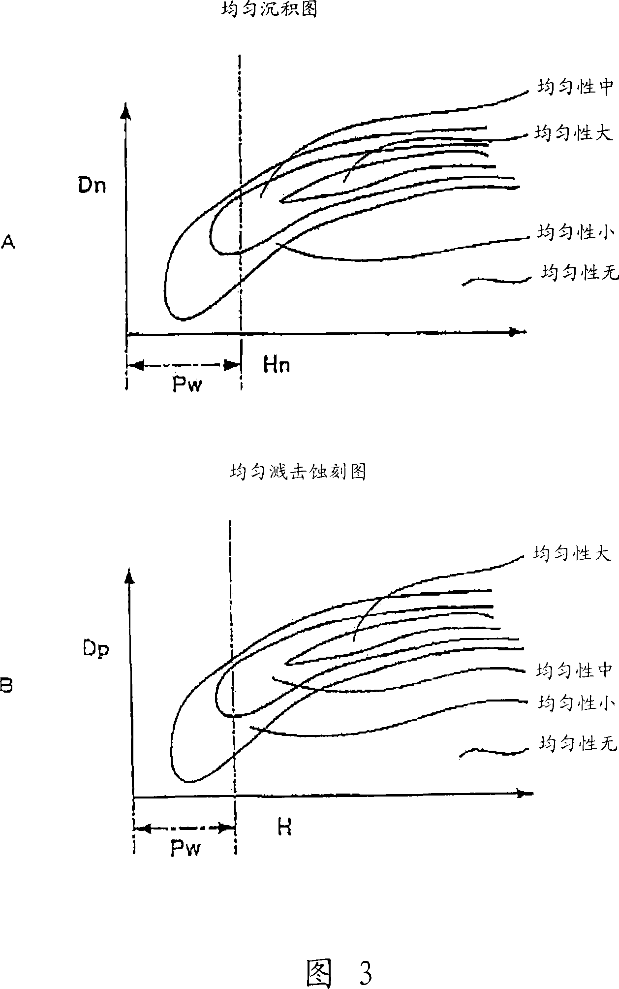
[0026]A first embodiment of the plasma processing apparatus of the present invention will be described with reference to FIGS. 1 to 4 . Fig. 1 is a schematic configuration diagram of a plasma processing apparatus; Fig. 2 is an explanatory diagram of main parts of the plasma processing apparatus of Fig. 1; A in Fig. 3 is a uniform deposition map, which is stored in the control of the plasma processing apparatus of Fig. 1 In the device, B is a uniform sputter etching map, which is stored in the control device of the plasma processing device in FIG. 1; FIG. 4 is a flowchart showing the sequence of the plasma processing method.

[0027] As shown in FIG. 1 , an elevating device 121 as an elevating mechanism is provided below the inside of a cylindrical vacuum reaction chamber 111 to which an exhaust pump 112 , which is an exhaust mechanism, is connected. In the lifting device 121 , a disk-shaped support table 113 for supporting the substrate 1 is installed so as to be coaxial with ...

no. 2 Embodiment approach

[0042] 5 to 7 are schematic representations of a plasma processing apparatus according to a second embodiment of the present invention. 5 is a schematic configuration diagram of a plasma processing apparatus, FIG. 6 is an explanatory diagram of main parts of the plasma processing apparatus of FIG. 5 , and FIG. 7 is a flow chart showing the procedure of a plasma processing method. Furthermore, regarding the parts that are the same as those of the above-mentioned first embodiment, since the symbols used here are the same as those used in the above-mentioned first embodiment, the parts that overlap with the description of the above-mentioned first embodiment will be omitted here. .

[0043] As shown in FIG. 5 , on the inner bottom surface of the vacuum reaction chamber 111 , a cylindrical support platform 213 for supporting the substrate 1 is provided, which is coaxial with the vacuum reaction chamber 111 . On the top of the vacuum reaction chamber 111, a plurality of ring-shape...


PUM


Abstract

When a size of a substrate (1) is instructed, a plasma processing apparatus reads a map, which shows a range where uniform sputter etching can be performed based on a relationship between a diameter size (Dp) of a high density plasma region and a height (H) between a center of the high density plasma region and a lower section in a plasma diffusion region. Based on an inner pressure and a frequency of an electromagnetic wave from an antenna (116), a height (Hp) between the center of the high density plasma region and an internal upper plane of a vacuum chamber (111) and the value (Dp) are obtained. Based on the inner pressure and a self-bias potential of the substrate (1), a height (Hs) between a lower section in the plasma diffusion region and an upper plane of a supporting table (113) are obtained, and based on the values of (Dp), (Hp) and (Hs), the value (H) showing the range where the uniform sputter etching can be performed is obtained from the map, and a lifting apparatus (121) is controlled so as to be at the value (H).

Description

technical field [0001] The present invention relates to a plasma processing device for generating plasma and processing the surface of a substrate. Background technique [0002] FIG. 8 shows an example of a conventional plasma processing apparatus that generates plasma and processes the surface of a substrate. [0003] As shown in Figure 8, the cylindrical vacuum reaction chamber 11 is connected with the exhaust pump 12, and the inner bottom surface of the vacuum reaction chamber 11 is provided with a cylindrical support platform 13 for supporting the substrate 1, which is coaxially arranged with the vacuum reaction chamber 11. . Above the above-mentioned support table 13 inside the vacuum reaction chamber 11, a plurality of main supply nozzles 14 are arranged at fixed intervals in the circumferential direction of the vacuum reaction chamber 11, and the front ends of the main supply nozzles 14 face the axial center of the vacuum reaction chamber 11. , transporting silane (...

Claims


Application Information

Patent Timeline
Patent Type & Authority Applications(China)
IPC IPC(8): H01L21/31H01L21/3065
CPCH01J37/32568H01J37/32009H01J37/32935H01L22/20H01L21/3065H01L21/02
Inventor 松田竜一井上雅彦
Owner MITSUBISHI HEAVY IND LTD
Why Eureka
Try Eureka