Stamping semi-module of forming die

A molding die and molding technology, applied in the direction of molding tools, metal processing equipment, manufacturing tools, etc., can solve the problems of the difficulty of setting wire and the loss of blanks, and achieve the effect of improving the speed of mold clamping and the quality of product production.

Inactive Publication Date: 2007-08-01
刘顺峰
View PDF0 Cites 0 Cited by
  • Summary
  • Abstract
  • Description
  • Claims
  • Application Information

AI Technical Summary

Problems solved by technology

Due to the high requirements for the cooperation between the slot hole and the setting wire in the actual operation process, especially the end of the slot hole connected to the mold cavity, the hole shape and the setting wire must be matched with high precision to prevent mold The blank is lost in the cavity, which affects the pressing of the blank
Since the matching precision between the slot hole and the setting wire is very high, it is very difficult to accurately place the setting wire in the slot hole when the two stamping halves are closed.

Method used


Image

  • Stamping semi-module of forming die
  • Stamping semi-module of forming die

Examples


Embodiment Construction

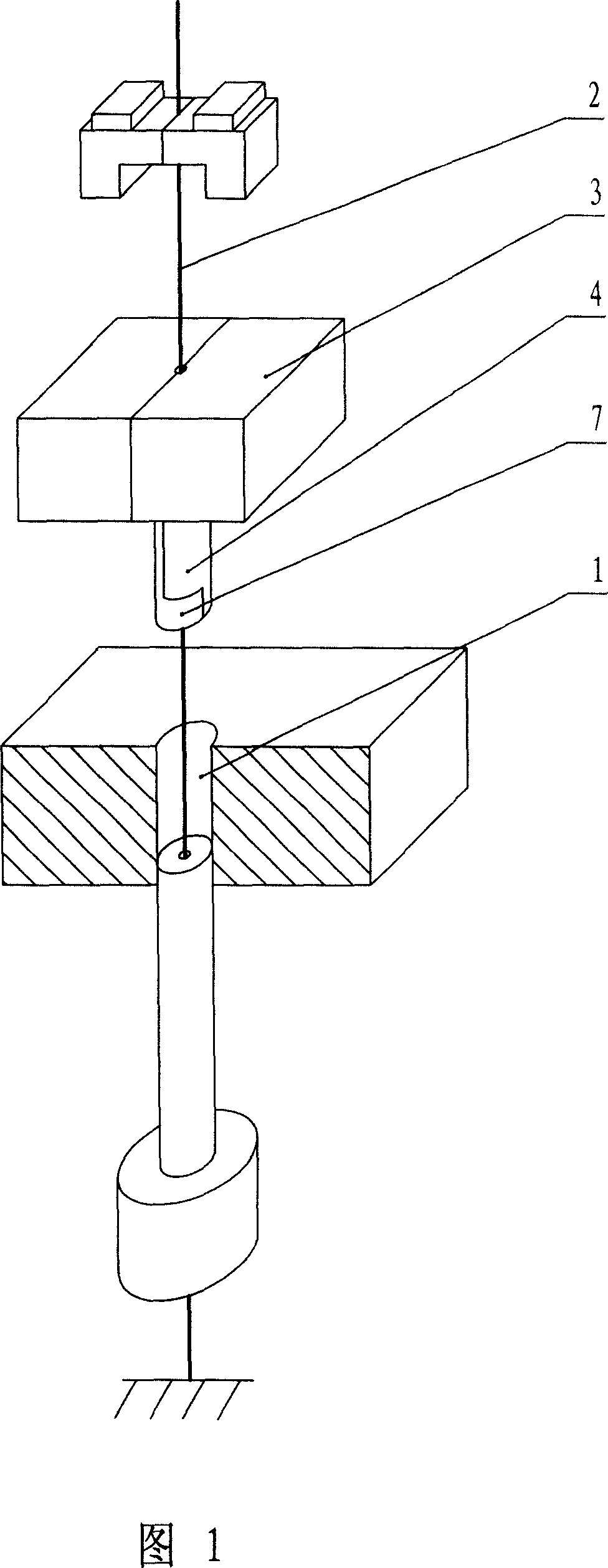
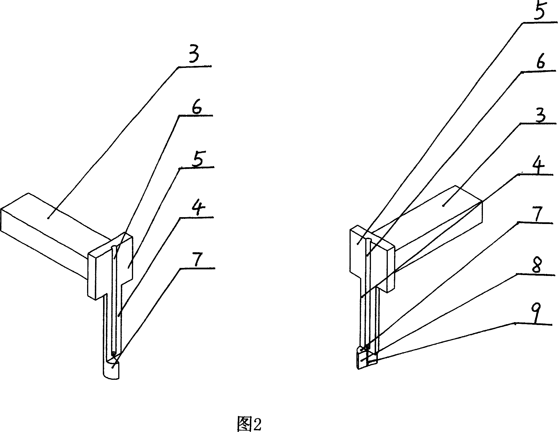
[0010] As shown in Figures 1 and 2, a stamping half-mold of a molding die includes a setting wire 2 pierced in the mold cavity 1, and a pair of opening and closing half-molds 3 arranged above the mold cavity 1. The two opening and closing halves The corresponding side ends of the mold 3 are respectively provided with a pair of half-molding rods 4 corresponding to each other, and the corresponding side planes 5 of the half-molding rods 4 are respectively provided with wire grooves 6 through up and down, and the ends of the half-molding rods 4 The half-molding heads 7 which are integrated with the half-molding rods 4 are respectively arranged, and the side planes 8 corresponding to the two halves of the molding heads 7 are also provided with wire grooves 9. The angle between the side plane 5 and the side plane 8 on the mold 3 can usually be between 90 degrees and 180 degrees at the same time, but in actual use, the angle is preferably between 92 and 150 degrees; in addition, the ...


PUM

PropertyMeasurementUnit
angleaaaaaaaaaa
angleaaaaaaaaaa

Abstract

The invention discloses a semi-stamping die of shaping die. It includes shaping wires crossing die cavity and a pair of folding semi-die installed at the top of die cavity; the side ends corresponding with two folding semi-dies are equipped with a pair of semi-die pressure bar matching and corresponding each other, the side plane corresponding with semi-die pressure bar is equipped with slots which through from up to down, the end of said semi-die pressure bar is equipped with semi-die pressure head connected with semi-die pressure bar into one unit, the side plane corresponding with two semi-die pressure heads is equipped with slots which through from up to down and between each other, the angles between side planes which lays same folding semi-die both are between 90 to 180 degrees; its advantages are: when the semi-stamping die damps, it can position the shaping wires in the slotted hole of slots automatically, quickly and accurately, thereby enhances the speed of clamping die and production quality of products.

Description

technical field [0001] The invention relates to a structure of a molding die, in particular to a stamping half-mold structure for accommodating and positioning setting wires in the molding die. Background technique [0002] Existing molding dies usually include a mold cavity, a set wire threaded in the mold cavity, a pair of punching half-molds corresponding to each other are arranged above the mold cavity, and half-mold pressure rods are respectively arranged on the adjacent side ends of the two punching half-molds. , the corresponding side planes between the two halves of the molded rods are respectively provided with slots through up and down. When the stamping half-molds are closed, the two corresponding slots can be surrounded into a slot for accommodating the setting wire. When in use, the setting wire The two ends of the die are tightened and fixed, the blank is put into the die cavity and then stamped or extruded by the half-mold rod on the stamping half-mold. Due t...

Claims


Application Information

Patent Timeline
Patent Type & Authority Applications(China)
IPC IPC(8): B21D37/12B21D22/02
Inventor 刘顺峰黄光荣
Owner 刘顺峰
Why Eureka
Try Eureka