Compensation test self-positioning bionic manipulator

A manipulator and self-positioning technology, used in manipulators, chucks, manufacturing tools, etc., can solve the problems of low rigidity, uneconomical, and long use time, and achieve the effect of improving work efficiency, not damaging materials, and grasping and kneading.

Pending Publication Date: 2019-12-03
WEIHAI GUANGWEI PRECISION MACHINERY
View PDF0 Cites 0 Cited by
  • Summary
  • Abstract
  • Description
  • Claims
  • Application Information

AI Technical Summary

Problems solved by technology

[0002] At present, there are two grabbing methods for steel mesh materials: finger manipulator and electromagnetic sucker. The finger manipulator mainly relies on finger gripping or back support to grasp the steel mesh material. The finger manipulator is suitable for grabbing grids with equal sizes and uniform sizes. Because the overall rigidity of the actual steel mesh material is not high and the mesh size is different, it is difficult for the fingers of the finger-shaped manipulator to insert the mesh accurately at one time, and even if the mesh is inserted, it is difficult to quickly and accurately grasp the wire mesh. Steel wire, there is a problem that it is difficult to grab and take a long time. The electromagnetic chuck converts electrical energy into electromagnetic force and uses the sucker to suck the steel wire of the wire mesh material to complete the grab. When grabbing, the sucker needs to be in contact with the steel wire of the wire mesh material. , in order to meet the grasping requirements, it is necessary to increase the area of ​​the electromagnetic chuck or increase the number of electromagnetic chucks, which will cause the electromagnetic chuck to be too large and heavy, and the increase in the number of electromagnetic chucks will greatly increase the procurement cost, which is very uneconomical

Method used


Image

  • Compensation test self-positioning bionic manipulator
  • Compensation test self-positioning bionic manipulator
  • Compensation test self-positioning bionic manipulator

Examples


Embodiment Construction

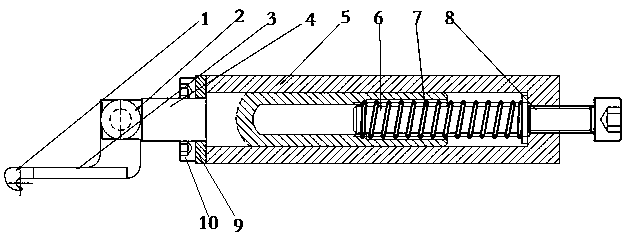
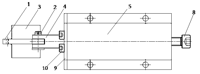
[0011] The present invention includes a mantis hand 1, a mantis arm 4 and a body 5. The front and rear sides of the body 5 are processed with circular through-holes, the periphery of the guide counterbore on the left end of the body 5 is processed with threaded counterbores, and the left end of the body 5 is guided to the bottom of the counterbore. There is a threaded hole connecting the right end face. The right arm body of Mantis Arm 4 is processed with a counterbore with steps. There is a circular through hole on the side of the groove of the head of the connecting rod on the left side of Mantis Arm 4. One end of Mantis Arm 1 is the one extending downward. Arc-shaped grab hook, the other end of the mantis 1 is a vertical rectangular steel plate processed with a circular through hole, the two sides of the mantis 1 are welded with a limit plate 3, and the counterbore of the steps is equipped with a compression spring 7 and a mandrel 6. Insert the body of the 4 arm into the gui...


PUM


Abstract

The invention relates to a compensation test self-positioning bionic manipulator, and belongs to the technical field of mechanical grabbing devices. The bionic manipulator comprises mantis hands, mantis arms and a machine body; threaded counter bores are machined around guide counter bores in the left end face of the machine body. A threaded hole connected with the right end surface is formed in the bottom of the machine body left end surface guide counter bore; a stepped counter bore is formed in an arm body of the mantis arm; a groove in a mantis arm connecting rod is provided with a circular through hole, the mantis hand is provided with a claw hook and a limiting plate; the mantis arm body with a compression spring and a mandrel that are installed in the stepped counter bore is inserted into a machine body guide counter bore, an end cover is fastened to the left end face of the machine body through a bolt; the mantis hand is hinged to the mantis arm through a pin shaft, and an adjusting bolt is screwed in the threaded hole of the machine body; the manipulator is based on a bionics principle, and designed by simulating a motion of the mantis forearm grabbing a prey; the bionic manipulator is simple in structure, low in cost, light in weight, convenient to install, capable of achieving kneading through grabbing force, free of damage to materials, capable of grabbing metal grid materials and non-metal grid materials, capable of achieving rapid, accurate and automatic positioning through mantis claw hooks in the working process and capable of greatly improving the working efficiency of the bionic manipulator.

Description

technical field [0001] The invention belongs to the field of mechanical grasping devices, in particular to a bionic manipulator with compensation and self-positioning. Background technique [0002] At present, there are two grabbing methods for steel mesh materials: finger manipulator and electromagnetic sucker. The finger manipulator mainly relies on finger gripping or back support to grasp the steel mesh material. The finger manipulator is suitable for grabbing grids with equal sizes and uniform sizes. Because the overall rigidity of the actual steel mesh material is not high and the mesh size is different, it is difficult for the fingers of the finger-shaped manipulator to insert the mesh accurately at one time, and even if the mesh is inserted, it is difficult to quickly and accurately grasp the wire mesh. Steel wire, there is a problem that it is difficult to grab and take a long time. The electromagnetic chuck converts electrical energy into electromagnetic force and u...

Claims


Application Information

Patent Timeline
Patent Type & Authority Applications(China)
IPC IPC(8): B25J15/00B25J15/02B25J15/08
CPCB25J15/00B25J15/0033B25J15/02B25J15/0253B25J15/08
Inventor 刘之乾白贤荣贾钊杨坤
Owner WEIHAI GUANGWEI PRECISION MACHINERY
Why Eureka
Try Eureka