Air filtering apparatus and control method therefor

A technology of air sterilization and control method, which is applied in air humidification system, air quality improvement, deodorization, etc., and can solve the problems of reduced sterilization effect and deviation

Inactive Publication Date: 2007-08-08
SANYO ELECTRIC CO LTD
View PDF1 Cites 2 Cited by
  • Summary
  • Abstract
  • Description
  • Claims
  • Application Information

AI Technical Summary

Problems solved by technology

[0004] However, in the existing ones, the concentration of active oxygen species in the water before electrolysis and the water after electrolysis is ...

Method used


Image

  • Air filtering apparatus and control method therefor
  • Air filtering apparatus and control method therefor
  • Air filtering apparatus and control method therefor

Examples


Embodiment Construction

[0026] Embodiments of the present invention will be described below with reference to the drawings.

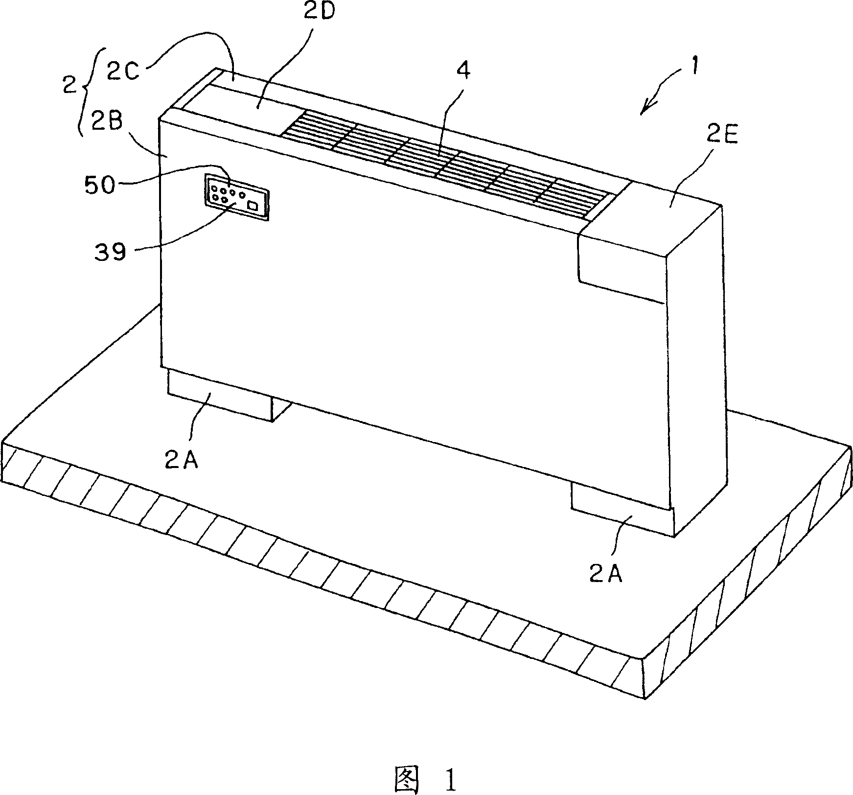
[0027] The floor-standing air sterilization device 1 is shown in FIG. 1 . The floor-standing air sterilization device 1 is equipped with a box-shaped frame body 2, which includes: a foot piece 2A, a front plate 2B, and a top plate 2C, and operation covers 2D and opening and closing covers are arranged in rows on both sides of the top plate 2C. 2E. A display screen 39 having a plurality of LEDs 50 for displaying various information is disposed on the upper left side of the front panel 2B.

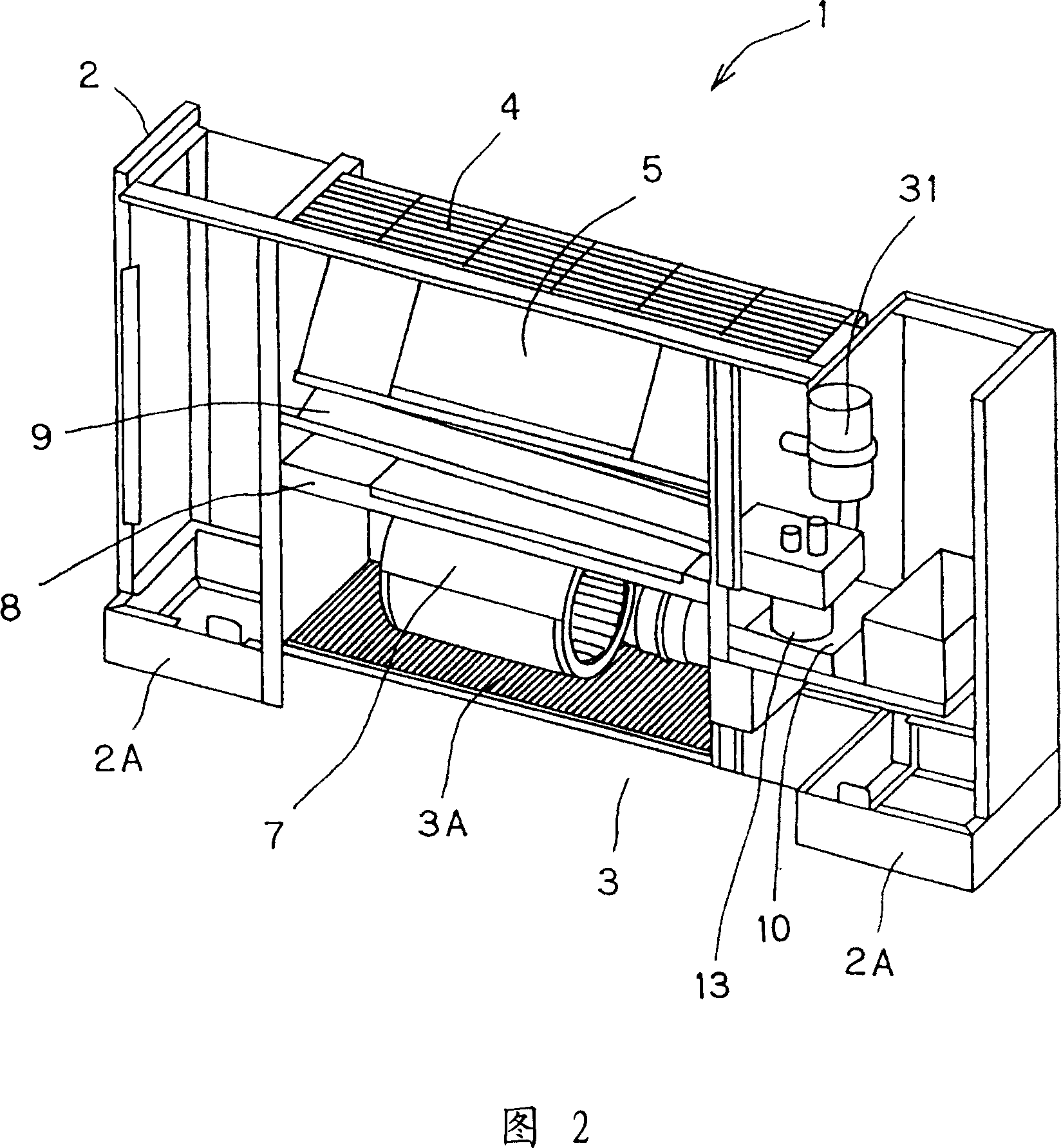
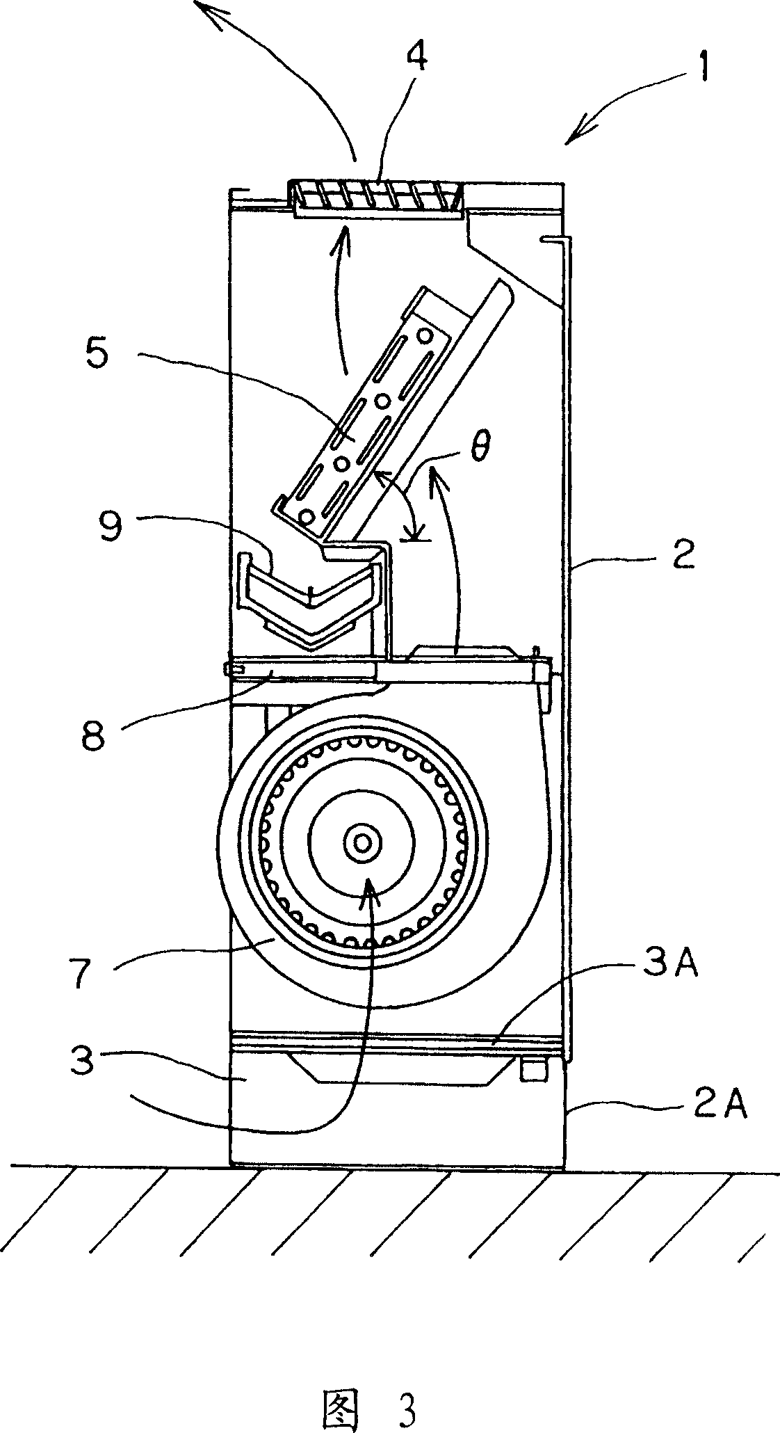
[0028] As shown in FIG. 2 , an air inlet 3 is arranged at the lower portion of the frame body 2 , and a prefilter 3A is arranged above the air inlet 3 . Above the prefilter 3A, the blowing fan 7 is supported by the housing 2 via the support plate 8 . The gas-liquid contact member 5 with high water retention is arranged obliquely above the support plate 8 as shown in FIG. 3 . A water rece...


PUM


Abstract

The invention provides a removing air bacteria device and the controlling method of the removing air bacteria device which can precisely control the reactive oxygen series concentration in the electrolysis water to be a target concentration. When the water is replaced and the time after the last time electrolysis operation is longer, a forward operating mode of electrolysis suitable for electrolyzing water before electrolyzed operates (from step Sa3 to step Sa7); when time after the last time electrolysis operation is shorter, a formal operating mode of electrolysis suitable for electrolyzing water after electrolyzed operates (from step Sa8 to step Sa12).

Description

technical field [0001] The invention relates to an air sterilizing device capable of removing airborne microbes and viruses and a control method thereof. Background technique [0002] Conventionally, electrolysis is performed to generate electrolyzed water containing active oxygen species, the electrolyzed water mist of the generated electrolyzed water is diffused in the air, and the electrolyzed water mist is directly contacted with airborne microorganisms to inactivate viruses, etc. A bacterial device has been proposed (for example, refer to Patent Document 1). [0003] Patent Document 1: JP-A-2002-181358 [0004] However, conventionally, the concentration of active oxygen species in the water before electrolysis and the water after electrolysis is very different. Therefore, depending on whether the water has been replaced, the concentration of active oxygen species varies, which reduces the sterilization effect. Contents of the invention [0005] An object of the pres...

Claims


Application Information

Patent Timeline
IPC IPC(8): A61L9/00
CPCF24F3/166F24F8/192Y02A50/20F24F3/16F24F6/00
Inventor 土桥光浩山本哲也
Owner SANYO ELECTRIC CO LTD
Why Eureka
Try Eureka