Air filter

An air filter and air inhalation technology, which is applied in the direction of fuel air filter, dispersed particle filtration, chemical instruments and methods, etc., can solve the problems of accelerated deterioration of the first component, improve maintainability, and inhibit mesh clogging , the effect of prolonging the service life

An air filter and air inhalation technology, which is applied in the direction of fuel air filter, dispersed particle filtration, chemical instruments and methods, etc., can solve the problems of accelerated deterioration of the first component, improve maintainability, and inhibit mesh clogging , the effect of prolonging the service life

CN101012788AInactive Publication Date: 2007-08-08HONDA MOTOR CO LTD

Image

  • Air filter
  • Air filter
  • Air filter

Examples


Embodiment Construction

[0025] Embodiments are described below with reference to the drawings.

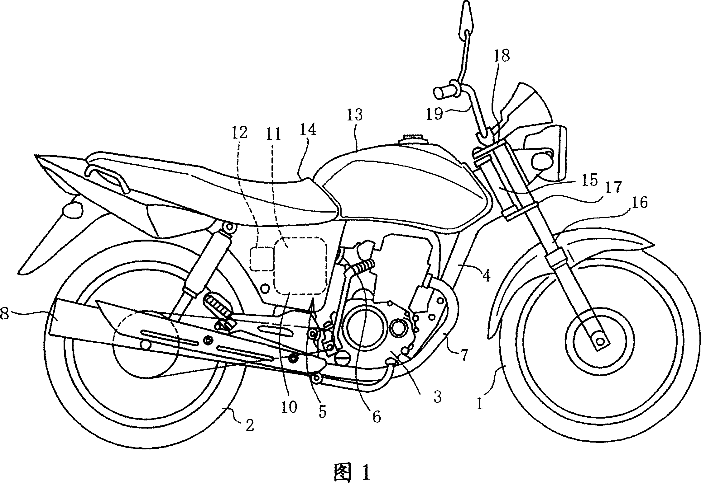
[0026] Fig. 1 shows the right side of a motorcycle equipped with the air cleaner device of the present invention.

[0027] An engine 3 disposed between the front wheels 1 and the rear wheels 2 is supported by a vehicle body frame 4 . Clean air is supplied to an intake port of the engine 3 from an air cleaner 5 arranged at the rear of the vehicle body through a connecting pipe 6 .

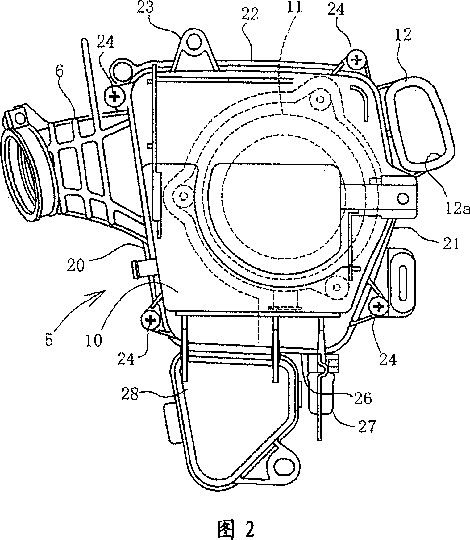
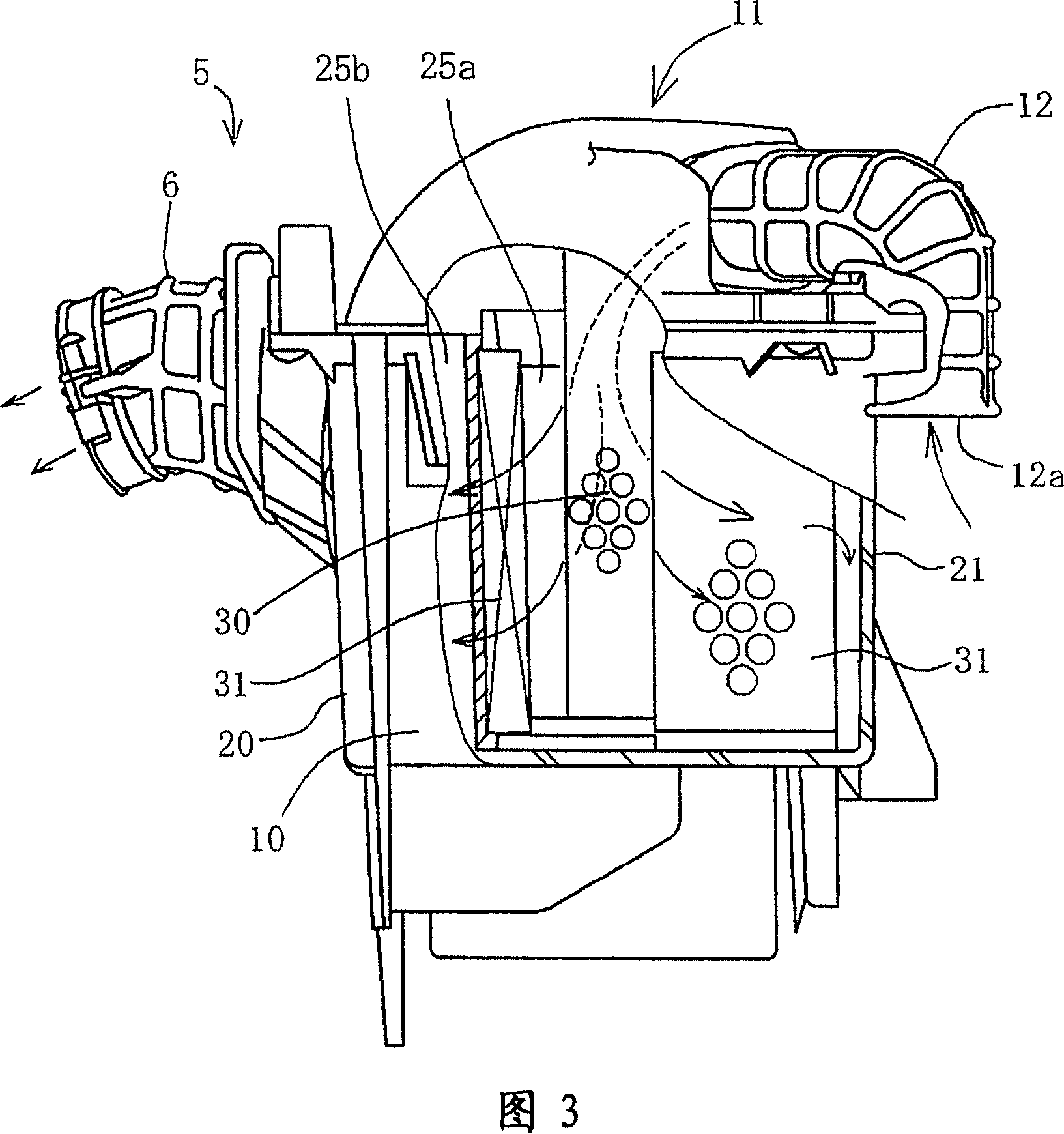
[0028] An exhaust pipe 7 protruding from an exhaust port of the engine 3 extends rearward through the bottom of the engine 3 and is connected to a muffler 8 arranged on the side of the rear wheel 2 . 10 is an air cleaner box of the air cleaner 5, 11 is an air cleaner cover, and 12 is a suction duct. The suction duct 12 faces the rear of the air cleaner box 10 and is opened inside the vehicle body, and sucks outside air into the air cleaner 5 from the rear of the vehicle body.

[0029] A fuel tank 13 is arranged above the eng...


PUM


Abstract

According to an air cleaner having a first element and a second element, the durability of the air cleaner element is improved and the ventilate resistance force for sucking air is reduced. An air cleaner (5) is formed by an air cleaner box (10) and an air cleaner cover (11), the air cleaner cover (11) supports the first element (30) on an element support part (35), the element support part (35) fixes one end to a cap shape body part (32) forming round shape. The first element (30) is mounted on the smudge side in the internal space of the second element (30) form a cylinder shape, and is seton the body part (32) and opposite to a suction port.

Description

technical field [0001] The present invention relates to an air cleaner used for an internal combustion engine of a motorcycle or the like, and more particularly to an air cleaner capable of improving the durability of elements. Background technique [0002] As a conventional air cleaner device, there is an air cleaner in which the air cleaner element is composed of a conical first element and a cylindrical second element, and the inside of the cylindrical portion of the second element is The space serves as the clean side, where the first element is housed and arranged, and dust is collected by sucking the outside air into the conical central part of the first element for a primary purification, and then all the primary purified air is pushed back toward the inflow direction to turn it into the The outer side of the cylindrical portion of the second element is passed through the cylindrical portion from the outer side to the inner side to collect dust and perform secondary c...

Claims


Application Information

Patent Timeline
08 Aug 2007
Publication
CN101012788A
IPC
F02M35/02
CPC
B01D46/0043; B01D46/2411
Inventors
中岛武久; 齐藤贤二郎