Air cleaner with reduced restriction precleaner

a precleaner and air cleaner technology, applied in the field of air cleaners, can solve problems such as undesirable restrictions, and achieve the effect of reducing entry restrictions and facilitating the location and centering of annular filter elements

Active Publication Date: 2005-10-25
CUMMINS FILTRATION INC
View PDF8 Cites 66 Cited by
  • Summary
  • Abstract
  • Description
  • Claims
  • Application Information

AI Technical Summary

Benefits of technology

[0002]Air cleaners with a tangential inlet and a precleaner are known in the prior art. Such air cleaners typically have a cylindrical housing and provide two stage cleaning, namely a precleaner provided by flow from the tangential inlet along a spiral path, and a second stage provided by radial inward flow through an annular filter element. The precleaner is typically provided by an annular sleeve circumscribing the annular filter element and spaced radially inwardly of the interior surface of the cylindrical sidewall of the housing by a radial gap defining an annular flow channel between the sleeve and the interior surface of the cylindrical housing sidewall

Problems solved by technology

While the sleeve provides the noted desirable functions, it also contributes to res

Method used


Image

  • Air cleaner with reduced restriction precleaner
  • Air cleaner with reduced restriction precleaner
  • Air cleaner with reduced restriction precleaner

Examples


Embodiment Construction

Prior Art

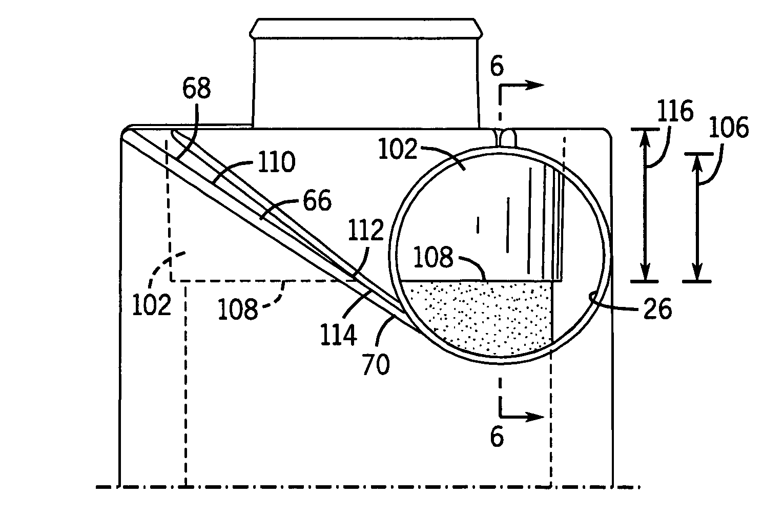
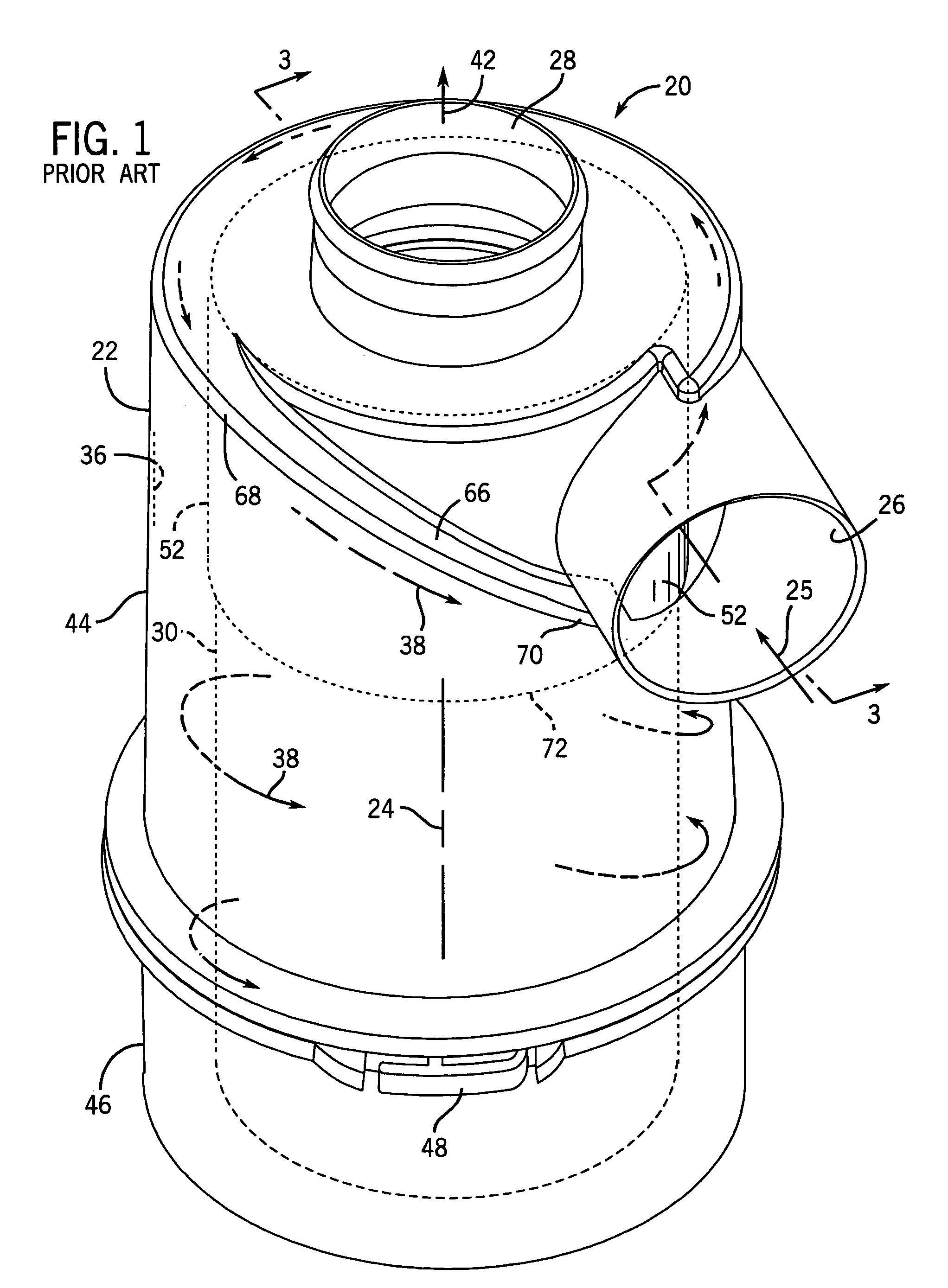
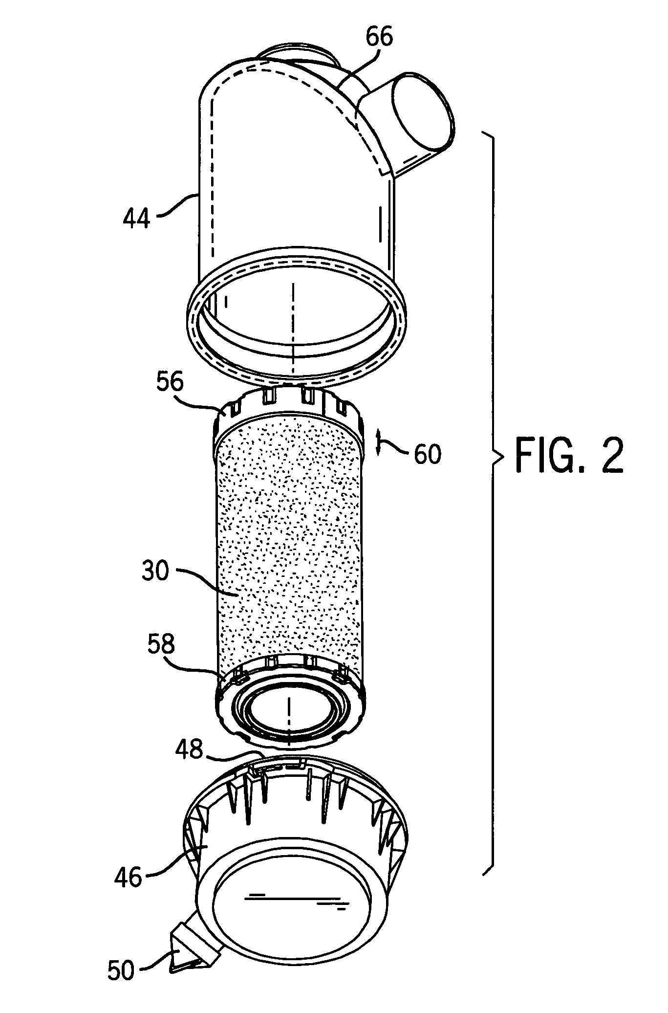
[0016]FIG. 1 shows an air cleaner 20 including a cylindrical housing 22 extending axially along an axis 24 and having a tangential inlet 26 and having an outlet 28. An annular filter element 30, FIGS. 2, 3, in housing 22 has a dirty side 32 receiving dirty air from inlet 26 and having a clean side 34 delivering clean filtered air to outlet 28. Air entering housing 22 through tangential inlet 26 as shown at arrow 25 flows along an interior surface 36 of housing 22 in a helical spiral pattern 38 about axis 24, and flows radially inwardly through annular filter element 30 into the latter's hollow interior 40 and then flows axially through outlet 28 as shown at arrow 42. Housing 22 is typically a two-piece plastic assembly provided by upper housing section 44 and lower housing section 46 joined by a twist and lock structure 48, for example as shown in U.S. Pat. No. 6,402,798, incorporated herein by reference. Lower housing section 46 may have a purge valve 50 for periodically d...


PUM

PropertyMeasurementUnit
Lengthaaaaaaaaaa
Depthaaaaaaaaaa
Heightaaaaaaaaaa

Abstract

An air cleaner is provided with a reduced restriction precleaner cooperating with a tangential inlet and centering and locating an annular filter element, and reducing inlet restriction.

Description

BACKGROUND AND SUMMARY[0001]The invention relates to air cleaners, and more particularly to air cleaners having a tangential inlet and a precleaner.[0002]Air cleaners with a tangential inlet and a precleaner are known in the prior art. Such air cleaners typically have a cylindrical housing and provide two stage cleaning, namely a precleaner provided by flow from the tangential inlet along a spiral path, and a second stage provided by radial inward flow through an annular filter element. The precleaner is typically provided by an annular sleeve circumscribing the annular filter element and spaced radially inwardly of the interior surface of the cylindrical sidewall of the housing by a radial gap defining an annular flow channel between the sleeve and the interior surface of the cylindrical housing sidewall. A ramp in the channel may direct air flow along a helical pattern. The sleeve also helps to locate and center the annular filter element within the housing. While the sleeve provi...

Claims


Application Information

Patent Timeline
IPC IPC(8): B01D46/24B01D46/00B01D46/02
CPCB01D46/0046B01D46/2411
Inventor SCHMITZ, KELLY R.RECH, JEFFREY A.
Owner CUMMINS FILTRATION INC
Why Eureka
Try Eureka