
Method of forming filter arrangements; and, apparatus

a filter arrangement and filter technology, applied in the field of air cleaners, can solve the problems of waste of materials and limited control of forming a planar surfa

Active Publication Date: 2009-08-04
DONALDSON CO INC
View PDF52 Cites 65 Cited by
  • Summary
  • Abstract
  • Description
  • Claims
  • Application Information

AI Technical Summary

Problems solved by technology

Thus, at the lead end or tail end of this region, the issue of concern would be the sealing of the fluted sheet to the facing sheet along this edge.
An issue with this approach is that it wastes material.
Also, control to form a planar surface may be limited by the ability to coil properly.

Method used


Image

  • Method of forming filter arrangements; and, apparatus
  • Method of forming filter arrangements; and, apparatus
  • Method of forming filter arrangements; and, apparatus

Examples


Embodiment Construction

I. Z-Filter Media Configurations, Generally

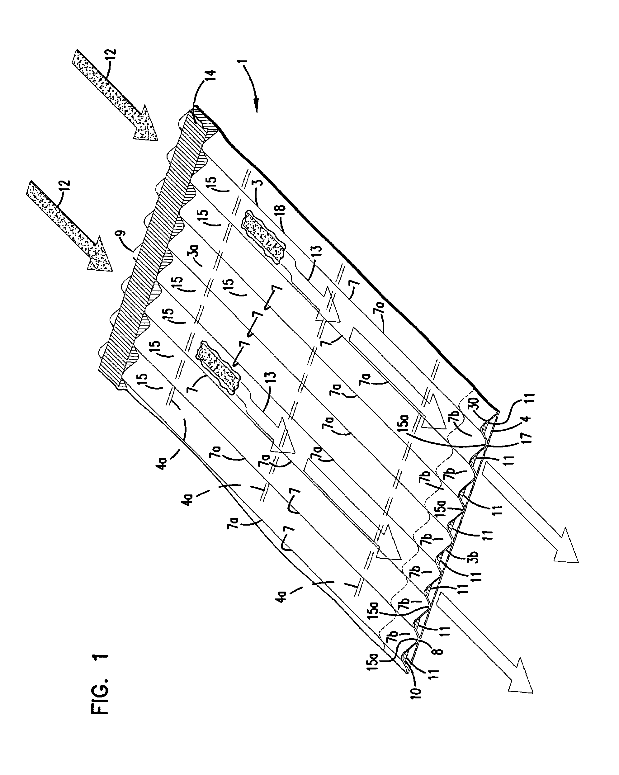
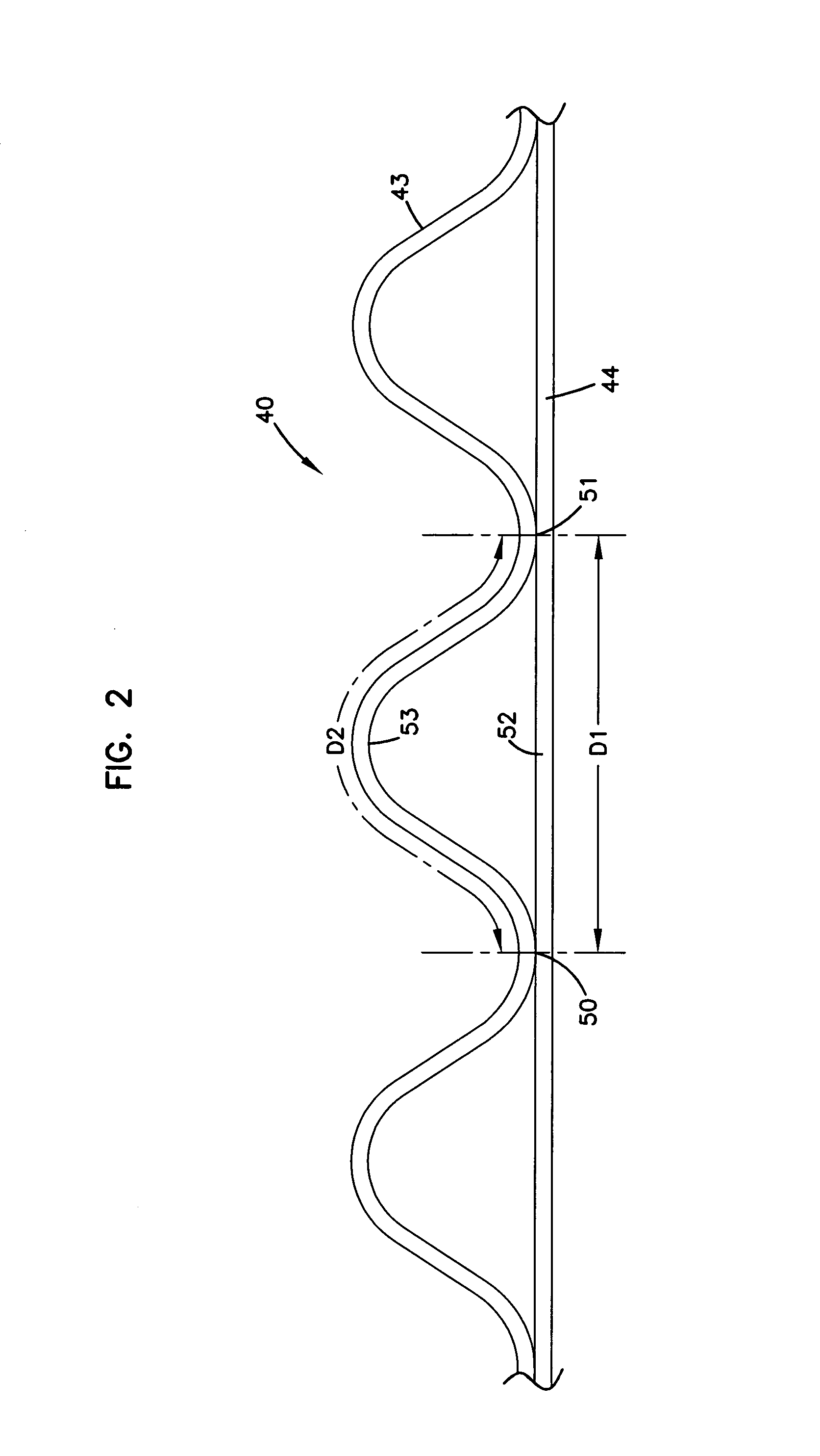
[0028]Fluted filter media can be used to provide fluid filter constructions in a variety of manners. One well known manner is as a z-filter construction. The term “z-filter construction” as used herein, is meant to refer to a filter construction in which individual ones of corrugated, folded or otherwise formed filter flutes are used to define sets of longitudinal, typically parallel, inlet and outlet filter flutes for fluid flow through the media; the fluid flowing along the length of the flutes between opposite inlet and outlet flow ends (or flow faces) of the media. Some examples of z-filter media are provided in U.S. Pat. Nos. 5,820,646; 5,772,883; 5,902,364; 5,792,247; 5,895,574; 6,210,469; 6,190,432; 6,350,296; 6,179,890; 6,235,195; Des. 399,944; Des. 428,128; Des. 396,098; Des. 398,046; and, Des. 437,401; each of these fifteen cited references being incorporated herein by reference.

[0029]One type of z-filter media, utilizes two speci...


PUM

PropertyMeasurementUnit
radiusaaaaaaaaaa
radiusaaaaaaaaaa
acute angleaaaaaaaaaa

Abstract

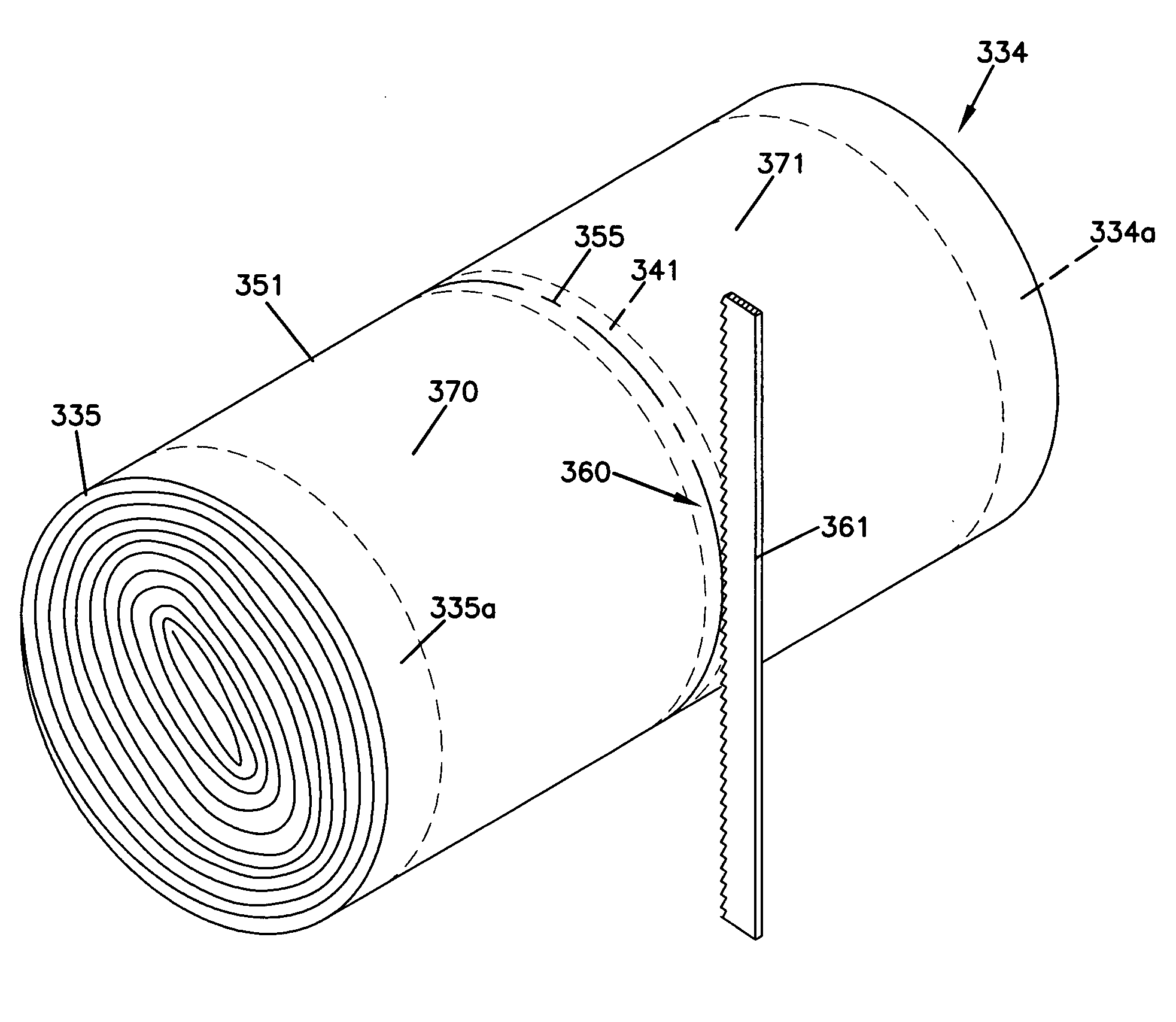
A one aspect method of forming filter cartridge arrangements for use in air cleaners is provided. The method involves coiling a media pack with a central winding bead and cutting through the winding bead in the coiled media pack to form two media packs. An example filter arrangement is disclosed. In another aspect, a filter cartridge arrangement for use in air cleaners is provided. The filter cartridge arrangement includes a media pack including a plurality of inlet flutes and outlet flutes extending between first and second opposite flow faces and formed from an arrangement of facing sheet secured to corrugated sheet. An example cartridge includes a preform secured to the media pack. In some forms, the preform includes a grid arrangement extending across one of the flow faces. The grid arrangement can include a region of cured seal material positioned in contact with the first flow face, to secure the grid arrangement to the flow face.

Description

CROSS-REFERENCE TO RELATED APPLICATION[0001]The present application includes the disclosures of, U.S. provisional application 60 / 627,603 filed Nov. 12, 2004 and U.S. provisional application 60 / 627,674 filed Nov. 12, 2004. Each of the two provisional applications is incorporated herein by reference, in its entirety. A claim of priority to each of the provisional applications is made, to the extent appropriate.TECHNICAL FIELD[0002]The present disclosure concerns air cleaners, for use, for example, for cleaning engine combustion air for vehicles and other equipment. The disclosure provides preferred components, assemblies and methods.BACKGROUND[0003]Gas streams often carry particulate material therein. In many instances it is desirable to remove some or all of the particulate material from the gas flow stream. For example, air intake streams to engines for motorized vehicles or power generation equipment often include particulate material therein. The particulate material, should it re...

Claims


Application Information

Patent Timeline
Patent Type & Authority Patents(United States)
IPC IPC(8): B01D29/07B01D29/48
CPCB01D46/0001B01D46/10B01D46/527B01D46/525Y10T156/1025B01D2279/60Y10S55/05B01D2271/027F02M35/02416F02M35/0245F02M35/02483B01D46/0005
Inventor NELSON, BENNY KEVIN
Owner DONALDSON CO INC
Learn More