Refuge operating apparatus in fire of group management elevator

A technology of operation device and group management, which is applied in the direction of transportation, packaging, elevators, etc., to achieve the effect of shortening the round-trip time

Inactive Publication Date: 2007-08-08
MITSUBISHI ELECTRIC CORP
View PDF2 Cites 11 Cited by
  • Summary
  • Abstract
  • Description
  • Claims
  • Application Information

AI Technical Summary

Problems solved by technology

[0004] However, in buildings in recent years, the fire protection section and other technologies have been improved, and the fire-occurring floor and the adjacent floors above it are rarely affected, and it does not matter even if the elevator continues to operate normally.

Method used


Image

  • Refuge operating apparatus in fire of group management elevator
  • Refuge operating apparatus in fire of group management elevator
  • Refuge operating apparatus in fire of group management elevator

Examples


Embodiment 1

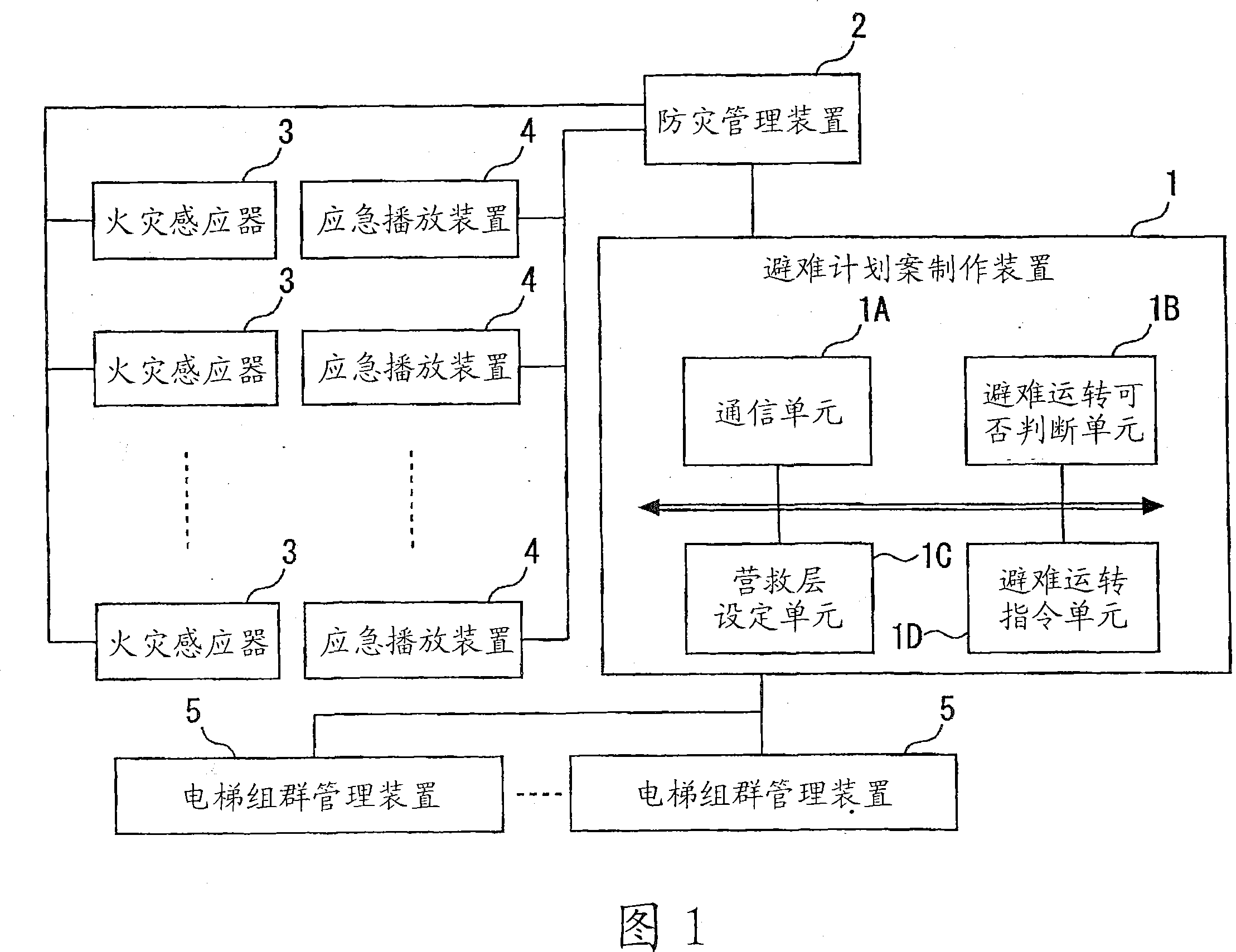
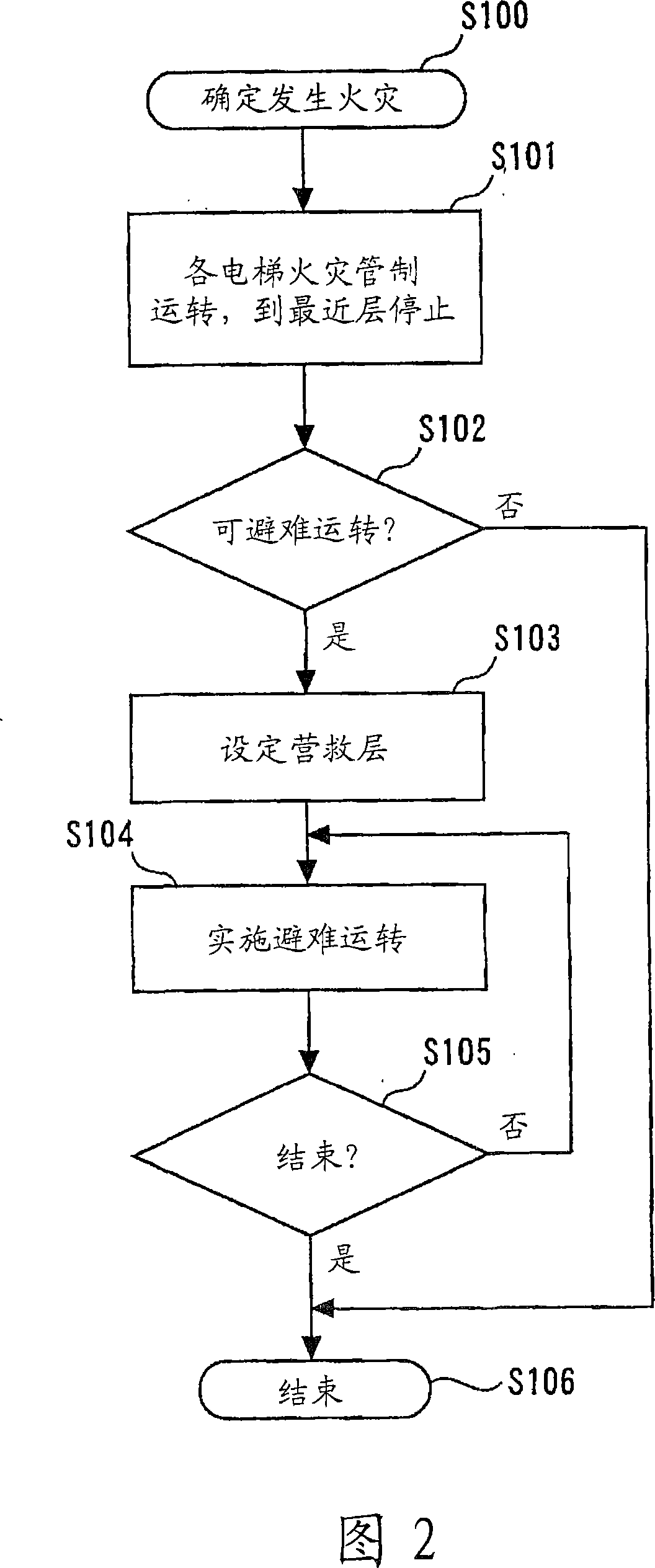
[0039]Next, a fire evacuation operation device for group-controlled elevators in Embodiment 1 of the present invention will be described. Fig. 1 is a block diagram showing an example of the overall configuration of functional categories of a fire evacuation operation device for group-controlled elevators in Embodiment 1 of the present invention. In Fig. 1, 1 denotes an evacuation plan preparation device, which prepares an evacuation plan for elevators and issues instructions; 2, a disaster prevention management device, which coordinates and manages disaster prevention equipment for the entire building; and 3, fire sensors installed on each floor ; 4 represents the emergency playback device that is also installed on each floor, and it implements announcements related to evacuation guidance in an emergency. In addition, 5 denotes an elevator group management device that manages and controls the elevator group.

[0040] Furthermore, the evacuation plan preparation device 1 of FI...

Embodiment 2

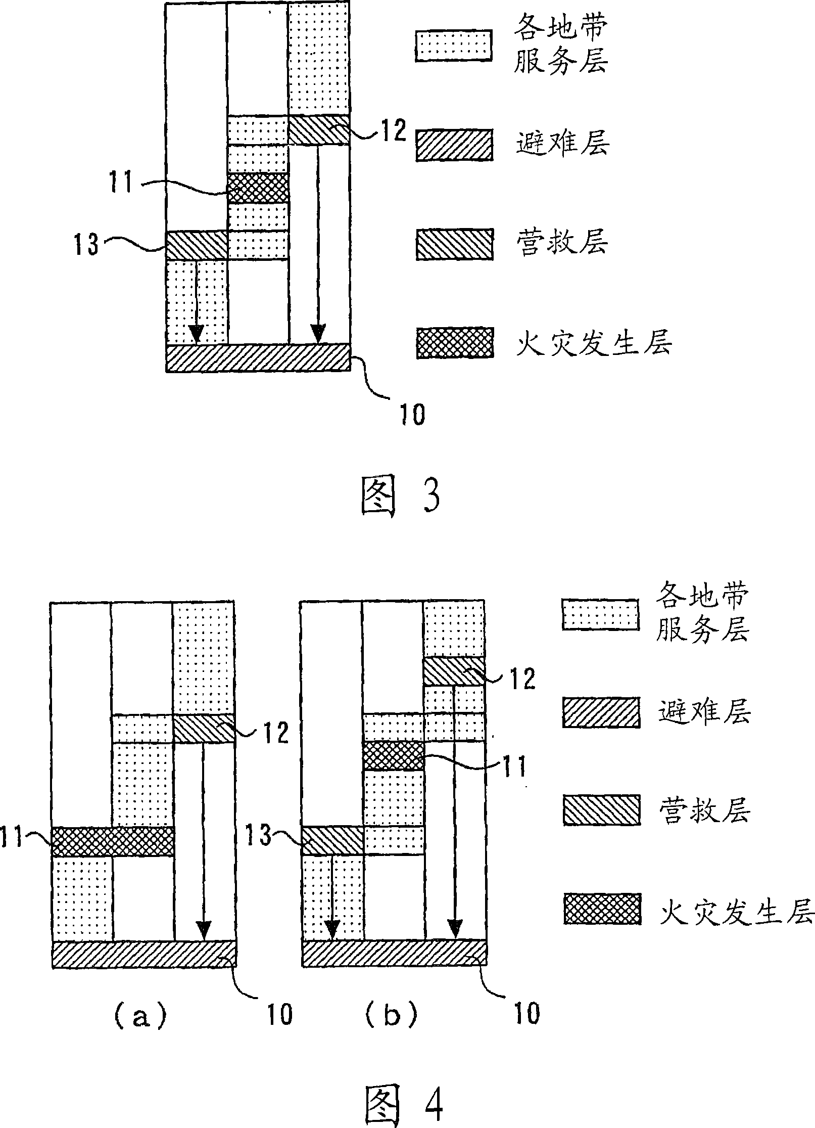
[0068] Next, a fire evacuation operation device for group-controlled elevators in Embodiment 2 of the present invention will be described. Fig. 5 is a block diagram showing an example of an overall configuration of functional categories of a fire evacuation operation device for group-controlled elevators in Embodiment 2 of the present invention. In FIG. 5 , the same reference numerals are assigned to the same parts as those in FIG. 1 , and description thereof will be omitted, and only differences will be described. 1E is the fire zone rescue floor setting unit, which sets the rescue floor when the elevator serving the zone including the fire zone performs evacuation operation according to the location of the fire zone; 1F is the non-fire zone rescue floor setting unit, which sets The rescue floor when the elevator serving the area excluding the fire outbreak floor performs evacuation operation.

[0069] Next, the operation in Embodiment 2 of the present invention will be desc...


PUM


Abstract

The invention relates to a fire evacuation operation device for group-controlled elevators, allowing a large number of people to evacuate in a short time. In the fire evacuation operation device for group-controlled elevators, the floors to be served are divided into service zones, the elevators serve from an entrance floor to each of the service zones, and when a fire detector placed at each floor detects fire, the device causes each elevator to stop at the nearest floor. The fire evacuation operation device has an evacuation operation possibility determination means (1B), a rescue floor setting means (1C), and an evacuation operation instruction means (1D). When a fire occurs, the evacuation operation possibility determination means (1B) determines that elevators serving a zone including a floor where the fire has occurred cannot perform evacuation operation, stopping operation of the elevators after they stop at the nearest floors, and also determines that elevators serving zones not including the floor where the fire has occurred can perform the evacuation operation. The rescue floor setting means (1C) sets, for the elevators that are determined to be able to perform the evacuation operation, rescue floors according to the floor where the fire has occurred. The evacuation operation instruction means (1D) assists evacuation of people in a building by making the elevators, determined to be able to perform evacuation operation, reciprocate between the entrance floor and the rescue floors.

Description

technical field [0001] The present invention relates to a fire evacuation operation device for group-controlled elevators, which can efficiently perform evacuation using elevators when a fire breaks out in a high-rise building. Background technique [0002] Usually, when a fire breaks out in a building, after each elevator travels to the nearest floor, the subsequent operation is often stopped. This is mainly for the purpose of preventing secondary disasters caused by elevators. That is, the fire control operation of a common elevator is as follows: When a fire occurs, in order to quickly evacuate the passengers who have already taken the elevator, the elevator is directly reached the evacuation floor, and in order to prevent the passengers from being closed, the door is kept open for a long time, and then, Prohibit the use of elevators in case of fire to prevent secondary disasters. [0003] In addition, different from ordinary elevators, there are emergency elevators wit...

Claims


Application Information

Patent Timeline
Patent Type & Authority Applications(China)
IPC IPC(8): B66B5/02
CPCB66B5/024
Inventor 匹田志朗河合清司
Owner MITSUBISHI ELECTRIC CORP
Why Eureka
Try Eureka