Method and system for interfacing communication networks

Active Publication Date: 2020-09-24
ANAPAYA SYST AG
View PDF0 Cites 1 Cited by
  • Summary
  • Abstract
  • Description
  • Claims
  • Application Information

AI Technical Summary

Benefits of technology

[0026]Hence, it is made sure that a second node is selected that is located in rather close vicinity to a specific destination

Problems solved by technology

Due to protocol incompatibilities, existing IP-capable devices cannot directly communicate over

Method used


Image

  • Method and system for interfacing communication networks
  • Method and system for interfacing communication networks
  • Method and system for interfacing communication networks

Examples


Example

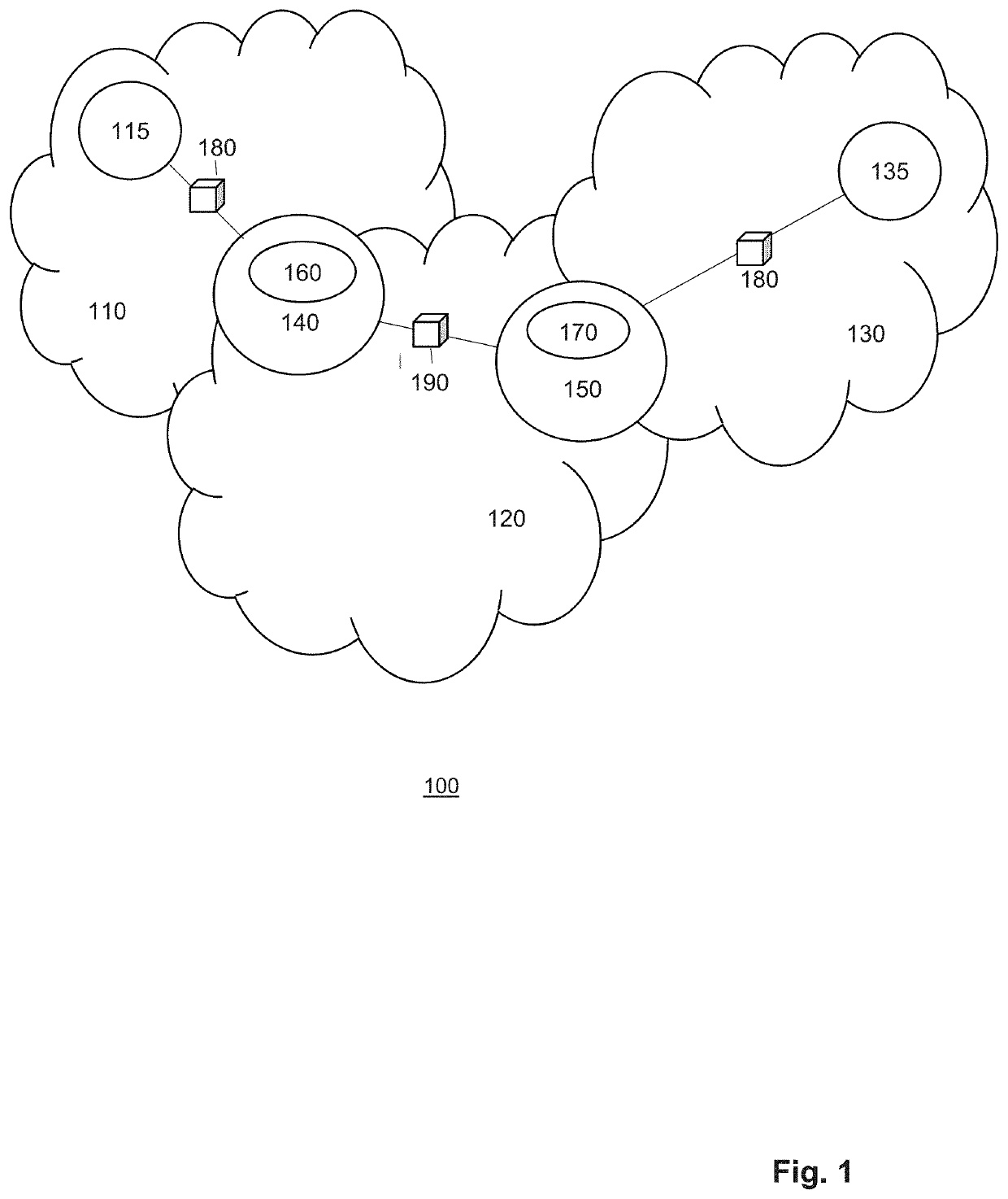
[0043]FIG. 1 shows the general architecture of a system 100 according to the present invention. Said system comprises a first packet switched network, in particular a first subnet 110, a source-selected path network 120, which is preferably implemented as a SCION network, and a second packet switched network, in particular a second subnet 130. The first subnet 110 of a packet switched network contains a source node 115 and the second subnet 130 of a packet switched network contains a destination node 135. Further, the system 110 comprises a first node 140 and a second node 150.

[0044]The first node 140 and the second node 150 are common nodes, in particular edge nodes, of both the source-selected path network 120 and / or the packet switched network, in particular the first 110 and second subnet 130, respectively. Each of the first 140 and second node 150 may, alternatively be thought of as two directly connected edge (sub-)nodes: a first edge (sub-)node 140 of the source-selected path...


PUM


Abstract

The invention is directed to a computer-implemented system and method for transmitting data from a first node to a second node of a source-selected path routing network. In said system and method according to the present invention, a first data packet is received at the first node, wherein said data packet was sent from a source node according to next-hop routing. Subsequently, at least part of the data contained in the data packet is transmitted from the first node to the second node according to source-selected path routing. Finally, the data received at the second node is transmitted to a destination node according to next-hop routing. Said system and method is further characterized by the steps of determining, for at least a subset of a plurality of available paths between the first node and the second node, a plurality of path parameters; determining a plurality of attributes related to the first data packet; selecting a preferred path from the plurality of available paths based on a decision rule, said decision rule specifying, for at least one attribute, a preferred range of path parameters; and remotely determining the second node based on destination information related to the destination node, wherein said destination information is extracted from the data packet.

Description

FIELD OF THE INVENTION[0001]The invention pertains to the field of communication networks, in particular computer networks. In particular, it relates to a system and a method for interfacing packet switched networks with networks employing source-selected path routing.BACKGROUND OF THE INVENTION[0002]Most Internet traffic today consists of Internet Protocol (IP) packets. To send IP traffic, a host first determines an IP address of a given destination, often using a service such as Domain Name Service (DNS). The host then includes the IP address in an IP header section of a data packet and sends the packet to a nearby router. At this point, the host no longer has any control over the path the data packet will take to reach its destination; i.e., the data packet travels through a sequence of routers, each of said routers deciding where to send the packet based on the destination IP address (and possibly other packet contents). Such principle of data packet transport is sometimes refer...

Claims


Application Information

Patent Timeline
IPC IPC(8): H04L12/715H04L12/725H04L12/721
CPCH04L45/04H04L45/34H04L45/302H04L45/124H04L45/126H04L45/121
Inventor HITZ, SAMUELSHIRLEY, STEPHENCOSTEA, SERGIU
Owner ANAPAYA SYST AG
Why Eureka
Try Eureka