
Plasma display device

A plasma display and plasma technology, applied in the direction of tube structure parts, mixed gas absorption, solid cathode parts, etc., can solve the problem that impurity gas cannot be completely eliminated, discharge start voltage characteristics, driving voltage characteristics and gray scale characteristics. Adverse effects, etc. question

Inactive Publication Date: 2007-08-22
LG ELECTRONICS(NANJING) PLASMA CO LTD
View PDF0 Cites 1 Cited by
  • Summary
  • Abstract
  • Description
  • Claims
  • Application Information

AI Technical Summary

Problems solved by technology

This type of strip-type getter has already been activated during the sealing process, so there is also the disadvantage that the impurity gas generated during the actual exhaust process or gas injection cannot be completely eliminated.
Therefore, when the PDP is in operation, it will adversely affect the discharge start voltage characteristics, drive voltage characteristics, and gradation characteristics for the start of discharge during driving.

Method used

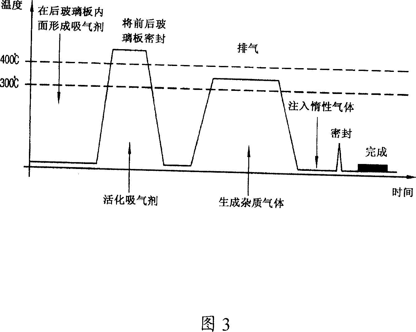

Image

  • Plasma display device
  • Plasma display device
  • Plasma display device

Examples


Embodiment Construction

[0038] Hereinafter, preferred embodiments of the present invention will be described in more detail with reference to the accompanying drawings.

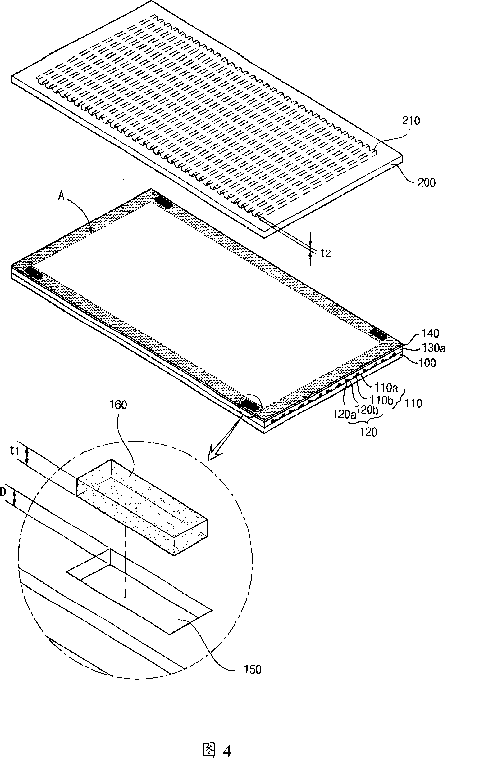
[0039] Fig. 4 is an exploded view of the PDP of the present invention. As shown in FIG. 4 , the PDP according to the present invention is the same as the prior art, and is formed by parallel bonding of the front glass plate 100 and the rear glass plate 200 of the display pixel by means of frit glass (not shown) at a certain distance.

[0040] The front glass plate 100 is composed of the following two parts: the sustain electrodes 110, 120 that rely on the mutual discharge of a pixel below to maintain the unit to emit light, that is, the transparent electrodes 110a, 120a formed by transparent ITO material; the bus electrodes 110b made of metal materials, Sustain electrodes 110, 120 at 120b. The protective layer 140 with the following functions is formed on the sustain electrodes 110, 120: form wall charges, maintain the discharge by...


PUM


Abstract

This invention relates to a plasma display combined in a certain distance by a front glass plate and a back one, in which, said front plate includes a space formed by the non-discharge region at the side in the front plate and a getter formed in the space characterizing: a, forming a display panel by combining the front glass plate forming more than one spaces in the non-discharge region in the inside surface and a back glass panel forming a getter entrance at the places corresponding to said more than one spaces, b, putting getter from the entrance of getters of the back glass plate and forming said getter in the spaces of the front glass plate, c, sealing the entrance of getters of the back plate, d, discharging impurities from the display panel, e, injecting discharge gas to the display panel.

Description

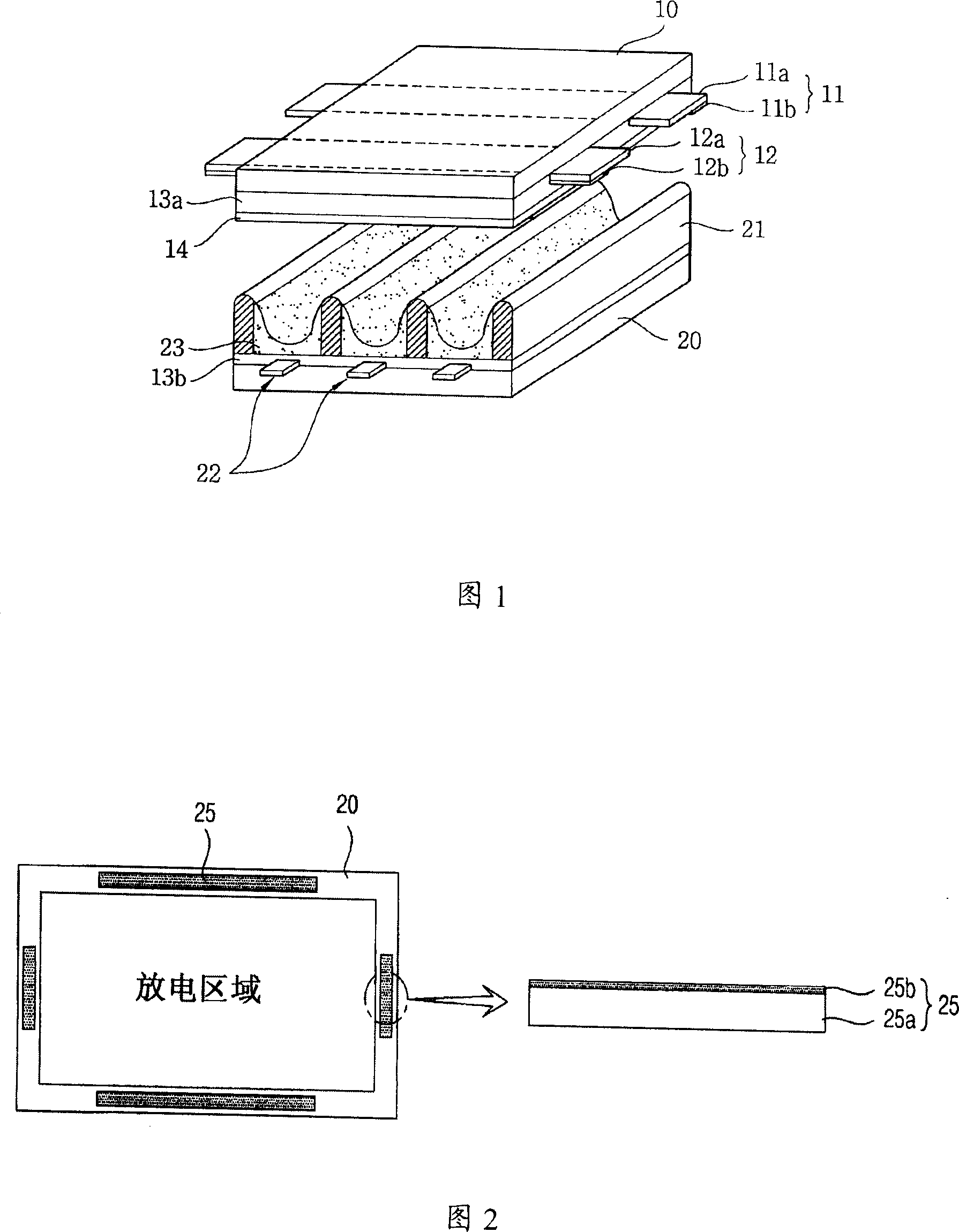
technical field [0001] The invention relates to a plasma display. In particular, it relates to a plasma display that improves the activity efficiency of a getter formed in order to remove impurity gases inside a display panel during the manufacture of a plasma display. Background technique [0002] Generally speaking, if a plasma display (Plasma Display Panel: hereinafter referred to as "PDP") is applied to the electrodes with alternating current (AC) or direct current (DC) voltage, a gas discharge will be caused between the electrodes. At this time, ultraviolet radiation is used to Phosphor emits light to display a screen. [0003] FIG. 1 is a structural diagram of an existing AC type PDP device. As shown in the figure, a PDP is formed by combining a display surface capable of displaying pictures, that is, a front glass plate 10 and a rear glass plate 20 forming a rear surface in parallel at a certain distance. [0004] The front glass plate 10 is composed of the followi...

Claims


Application Information

Patent Timeline
Patent Type & Authority Applications(China)
IPC IPC(8): H01J17/49H01J17/24H01J11/52
Inventor 朴宰范
Owner LG ELECTRONICS(NANJING) PLASMA CO LTD
Learn More