Ink jet printer discharge amount control method, ink droplet spread check method, and orientation film formation method

An inkjet printer, speed control technology, applied in printing, devices for coating liquid on the surface, optics, etc., can solve problems such as difficult orienting film materials, nozzle orientation nozzles being blocked by oriented film materials, nozzle defects, etc., to achieve correction Easy and Precise Effects

Active Publication Date: 2007-08-22
ISHII HYOKI
View PDF2 Cites 37 Cited by
  • Summary
  • Abstract
  • Description
  • Claims
  • Application Information

AI Technical Summary

Problems solved by technology

However, due to the inkjet method, problems such as nozzle defect, nozzle orientation, and nozzle clogging by the alignment film mat

Method used


Image

  • Ink jet printer discharge amount control method, ink droplet spread check method, and orientation film formation method
  • Ink jet printer discharge amount control method, ink droplet spread check method, and orientation film formation method
  • Ink jet printer discharge amount control method, ink droplet spread check method, and orientation film formation method

Examples


no. 1 approach

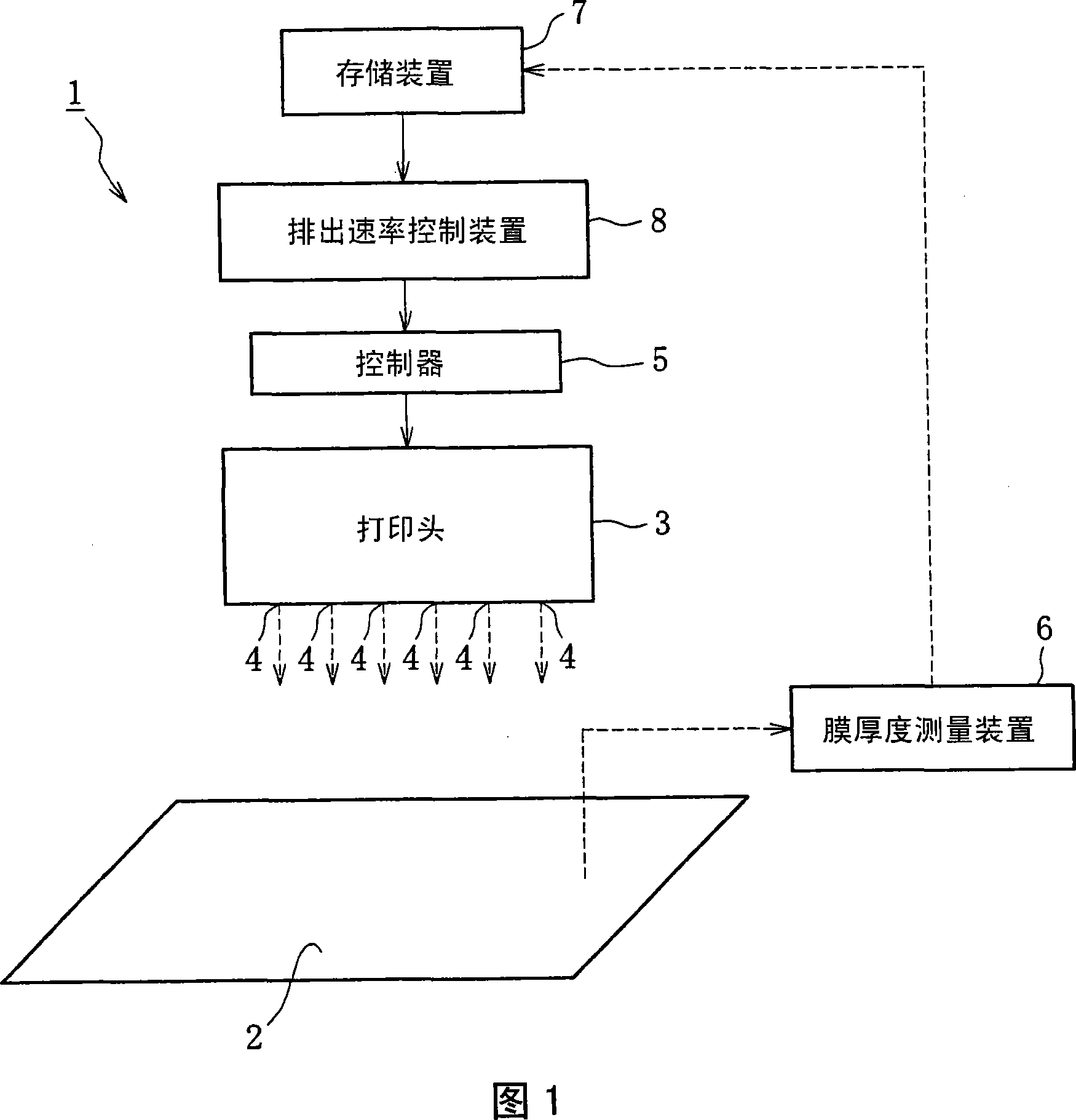
[0099] 1 to 11 are examples showing the first embodiment of the present invention. As shown in Figure 1, the main parts of the discharge rate control device 1 of an inkjet printer include: a transparent glass substrate 2, which is used in a liquid crystal display device, and has the property of not absorbing ink; a controller 5, which is used for Controlling the amount of ink discharged from the plurality of nozzles 4 of the print head 3; a film thickness measuring device 6 for measuring the thickness of the ink on the glass substrate 2 by the ink discharged from the print head 3 with respect to the discharge position of each nozzle 4 The thickness of the formed film. The discharge rate control apparatus 1 additionally includes: storage means 7 for storing correction corresponding to the difference between the target film thickness at the ink discharge position of each nozzle 4 and the film thickness determined by the film thickness measurement means 6 data; discharge rate co...

no. 2 approach

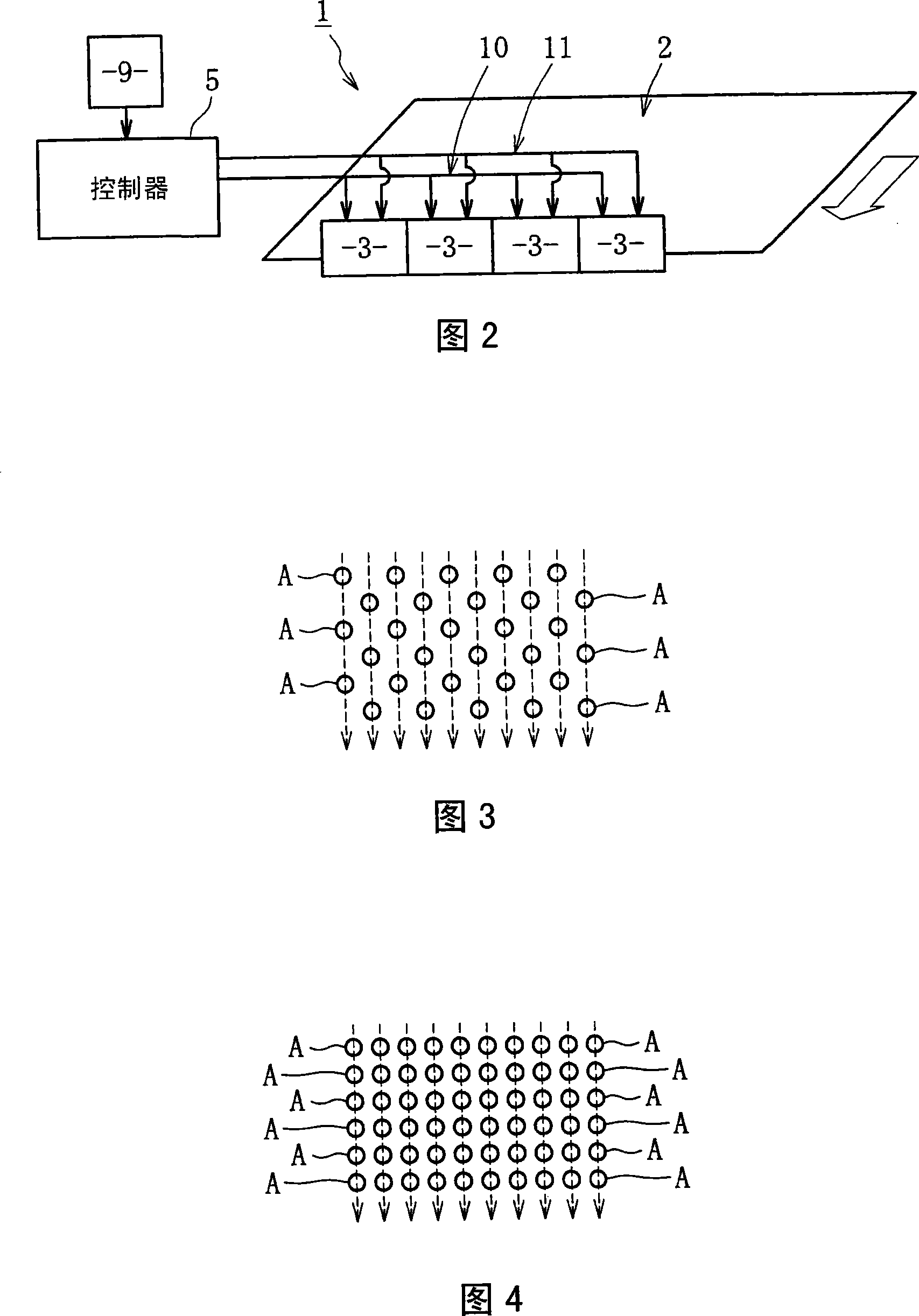
[0109] 12 to 18 are examples showing the second embodiment of the present invention. Fig. 12(a) is a schematic top view showing parts of an ink scatter inspection apparatus including an inkjet print head 1, a transparent type shown in solid lines and used as an inkjet printhead before being coated with a small ink droplet. The glass substrate 2 of the coating and the glass substrate 2 shown in dotted lines and used as the coating after being coated with small ink droplets (a group of small ink droplets 3), FIG. 12 (b) is shown in the same state A schematic side view of each component 1, 2 below. Fig. 13 is a schematic side view showing the arrangement of the inspection camera 4 and a plurality of lighting devices 5, 6 which are components of the ink scatter inspection apparatus.

[0110] According to the second embodiment, as shown in FIG. 12(a), (b), when the glass substrate 2 under the inkjet print head 1 held at a fixed position is moved toward the direction of the arrow, ...


PUM


Abstract

A discharge amount control method for an ink jet printer (1) includes: a film formation step for discharging ink onto an ink non-absorbing material-to-be-coated (2) from a plurality of nozzles (4) of a print head (3) so as to form a filmB on the material-to-be-coated; a film thickness measurement step for measuring the film thickness of the film B formed on the material-to-be-coated (2) in the film formations step in connection with the ink discharge position of each of the nozzles (4); and a discharge amount correction step for increasing/decreasing the ink discharge amount from each of the nozzles (4) according to the difference between the film thickness at the ink discharge position of each of the nozzles (4) measured in the film thickness measurement step and a target film thickness Ba.

Description

technical field [0001] The present invention relates to a technique for maintaining the consistency of the ejection rate of ink on an application from a plurality of nozzles on a printhead of an inkjet printer among the individual nozzles, a technique for checking ink scatter And a technique for forming an alignment film on a glass substrate using this ink. Background technique [0002] In recent years, in addition to printing on substrates made of paper, fibers, plastics, ceramics, etc. Inkjet printers are also used when coating color filters on transparent glass substrates in organic EL display devices. Specifically, in the case of a liquid crystal display device, an alignment film material such as transparent PI ink (transparent polyimide ink) or transparent UV ink is discharged and coated on a glass substrate (for example, see Patent Document 1), as far as In the case of an organic EL display device, a coating material such as transparent UV ink is discharged and coate...

Claims


Application Information

Patent Timeline
IPC IPC(8): B05D1/26B41J2/01B05C5/00G02F1/13
Inventor 中野辉幸小泽康博
Owner ISHII HYOKI
Why Eureka
Try Eureka