Thin ventilating louver

A ventilation skylight, thin technology, applied in the direction of skylight/dome, etc., can solve the problems of weak wind resistance, heavy load, complex structure, etc.

Inactive Publication Date: 2010-05-19
孙建和 +1
View PDF3 Cites 0 Cited by
  • Summary
  • Abstract
  • Description
  • Claims
  • Application Information

AI Technical Summary

Problems solved by technology

However, the existing ventilation skylight not only has a complex structure, but also has a heavy load, and the height of the ventilation skylight above the roof opening is relatively high, so the wind resistance is not strong

Method used


Image

  • Thin ventilating louver
  • Thin ventilating louver
  • Thin ventilating louver

Examples


Embodiment Construction

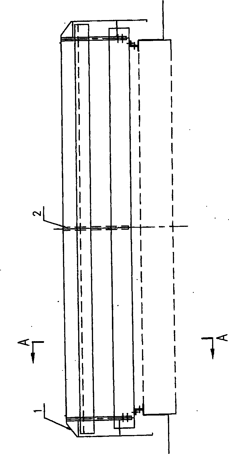
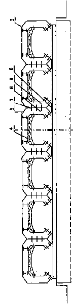
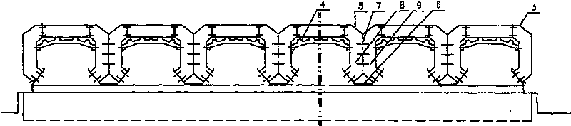
[0009] by figure 1 , figure 2 It can be seen that this kind of thin ventilation skylight consists of multiple rows of units arranged in parallel. Both ends of the multiple rows of units are provided with outer guard plates 1. The outer guard plates 1 are fastened to the frame 2 by couplings, and the outer units are provided with side panels. In the wind deflector 3, an upper rain deflector 5 is provided between adjacent units. The upper rain deflector 5 is supported by a partition 7, and the adjacent brackets 8, 9 are fastened to connect the adjacent units through the partition 7, The lower rain shield 4 is tightly connected to the bracket, and the water tank 6 is tightly connected to the adjacent brackets 8 and 9. Multiple rows of units are installed side by side on the roof opening and can be increased to any size in length. The upper rain shield 5 and the lower rain shield 4 can be made of color steel plate tiles. Since the present invention adopts an integrated structure...


PUM


Abstract

A dormer window is composed by multi units fixed side by side, with outer protective board fixed to the two ends of the units; a shield plate is fixed to the outer unit; an upper rain shield board isfixed between each unit, which is supported by clapboard; every two units are connected by brackets on the clapboard; a lower rain shield board is fixed with the brackets, and a water groove is fixedwith the brackets in neighbor.

Description

Technical field [0001] The invention relates to a ventilation device, in particular to a thin ventilation skylight (ventilator) used in various industrial plants. Background technique [0002] At present, combined roof ventilation skylights are mostly used in natural ventilation equipment for high-heat workshops. This type of ventilation skylights are mainly composed of windshields, rain shields, flood panels and valve plates. However, the existing ventilation skylights are not only complicated in structure and heavy load, but the height of the ventilation skylights above the roof opening is also relatively high, so the wind resistance is not strong. In the case of relatively strong wind, there will also be rain caused by wind around the ventilation skylight. Summary of the invention [0003] The technical problem to be solved by the present invention is to provide a ventilation skylight with simple structure and strong wind resistance. [0004] The technical problem to be solved ...

Claims


Application Information

Patent Timeline
Patent Type & Authority Patents(China)
IPC IPC(8): E04D13/03
Inventor 孙建和毛海林蔡鹏
Owner 孙建和
Why Eureka
Try Eureka