Inflating overpressure spill valve for vacuum

A relief valve and overpressure technology, applied in safety valves, balance valves, valve devices, etc., can solve the problems of unsuitable high vacuum environment, system component damage, system pressure explosion, etc., and achieve low cost, simple installation and debugging, good versatility

Inactive Publication Date: 2007-09-19
BEIJING ZHONGKEXIN ELECTRONICS EQUIP
View PDF0 Cites 11 Cited by
  • Summary
  • Abstract
  • Description
  • Claims
  • Application Information

AI Technical Summary

Problems solved by technology

[0003] This kind of nitrogen filling is a high-pressure gas. When the pressure in the vacuum chamber reaches atmospheric pressure, nitrogen can still be filled into the chamber. At this time, the internal pressure of the chamber will be higher than the external atmosphere, forming a positive pressure. If there is no overpressure overflow When the device overflows, the pressure in the chamber will continue to increase until it is balanced with the pressure of the air source. This high pressure is easy to damage some system components, and in severe cases, it will cause the system pressure to explode and cause personal injury.
There are similar products on the market, but they are generally not suitable for high vacuum environments.

Method used


Image

  • Inflating overpressure spill valve for vacuum

Examples


Embodiment Construction

[0020] The present invention will be further introduced below in conjunction with the accompanying drawings and specific embodiments, but not as a limitation of the present invention.

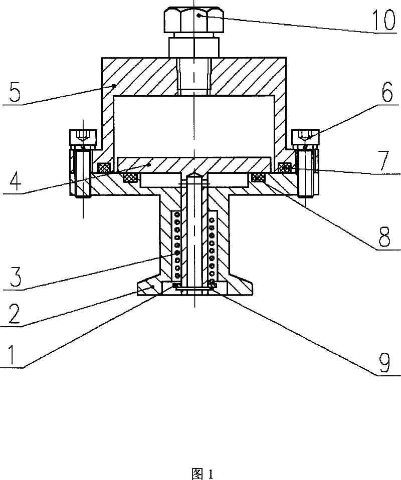
[0021] Referring to Figure 1, the main components of the vacuum relief valve device are: gasket 1, KF interface 2, spring 3, overflow sealing cover 4, outer cover 5, hexagon socket head screw 6, O-ring 7 and O-ring 8, circlip 9, ferrule joint 10.

[0022] The KF interface 2 is connected to the vacuum system, and the gas inflated enters from the through hole at the lower end of the overflow sealing cover plate 4, and the gas pressure acts on the overflow sealing cover plate 4. When the pressure is greater than the pre-pressure of the spring 3, the overflow sealing Cover plate 4 is jacked up, spring 3 is compressed, and overflows. When the air pressure at both ends of the overflow sealing cover 4 is balanced, under the elastic force of the spring 3, the overflow sealing cover 4 moves down to aut...


PUM


Abstract

The invention relates to a vacuum system over-pressure safety device for ion implantation apparatus, particularly a vacuum overpressure overflow valve, when the internal pressure is higher than a setup pressure, overflow exhausting is carried out automatically to prevent system element damage or pressure explosion due to the overpressure, which protects safe running of the vacuum system.

Description

technical field [0001] The invention is a vacuum pressure protection device, which is used to automatically overflow and exhaust when the internal pressure is higher than the set pressure when filling nitrogen into the vacuum system of the ion implanter, so as to prevent damage to some system components due to overpressure. The damage or pressure explosion will play a role in protecting the safe operation of the vacuum system. It belongs to the field of semiconductor equipment. Background technique [0002] The ion implanter is a kind of particle accelerator. The ions of the doped elements are ionized from the ion source, and then the required ions are screened out by the analyzer, and then the ion beam is scanned and accelerated, and finally reaches the target chamber and is injected into the silicon wafer. . The cavity of the ion movement process must be kept in a high vacuum environment. When maintaining the vacuum system, it is necessary to fill the vacuum chamber and...

Claims


Application Information

Patent Timeline
Patent Type & Authority Applications(China)
IPC IPC(8): F16K17/04
Inventor 唐景庭彭立波姚琛钟新华
Owner BEIJING ZHONGKEXIN ELECTRONICS EQUIP
Why Eureka
Try Eureka