Stacked flexible rack gear type elevating gear

A lifting device and rack-type technology, applied in the direction of lifting device, lifting frame, etc., can solve the problems of long rack processing cycle, poor interchangeability, and high maintenance cost, and achieve good coordination, reduced processing cycle, and good interchangeability. Effect

Inactive Publication Date: 2009-04-15
ZHEJIANG DAFENG IND
View PDF1 Cites 32 Cited by
  • Summary
  • Abstract
  • Description
  • Claims
  • Application Information

AI Technical Summary

Problems solved by technology

[0006] In order to overcome the shortcomings of long processing cycle, poor interchangeability and high maintenance cost of the rack in the lifting device in the prior art, the present invention provides a superimposed flexible rack type with reduced processing cycle, good interchangeability and reduced maintenance cost. lifting device

Method used


Image

  • Stacked flexible rack gear type elevating gear
  • Stacked flexible rack gear type elevating gear
  • Stacked flexible rack gear type elevating gear

Examples


Embodiment 1

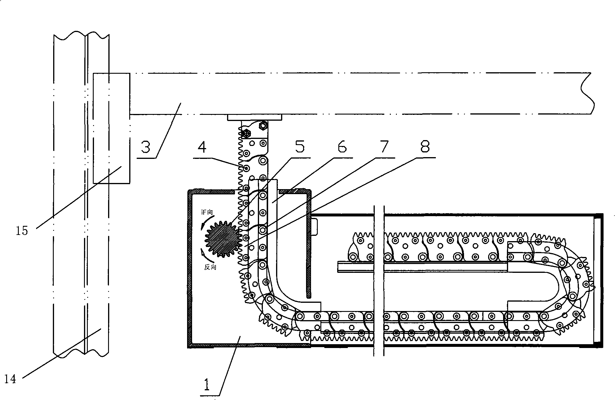
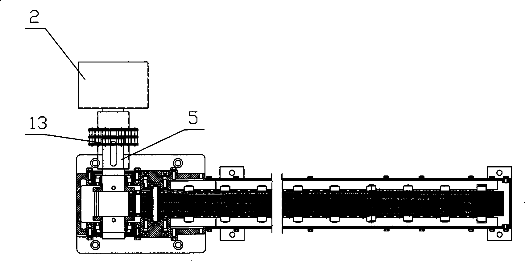
[0034] refer to figure 1 and figure 2 , a superimposed flexible rack type lifting device, including a fixed bracket 1, a driving device 2, a lifting bracket 3, and a flexible rack 4 for jacking up the lifting bracket, and a gear 5 is installed on the upper end of the fixed bracket 1 , the gear 5 is connected to the driving device 2; the flexible rack 4 is located in the fixed bracket 1, and the fixed bracket 1 is provided with a guide rail 6, the upper part of the guide rail 6 is in a vertical direction, and An arc-shaped extension section is provided to a horizontal position, and a pulley 7 cooperating with the guide rail is provided on the flexible rack 4, and the flexible rack 4 is a rigid chain formed by hinges of multiple gear blocks 8 , one side of the tooth block 8 has a tooth shape meshing with the gear, the adjacent teeth of the adjacent tooth blocks are spliced ​​into a complete tooth shape, and the adjacent tooth blocks are hinged to each other on the side without...

Embodiment 2

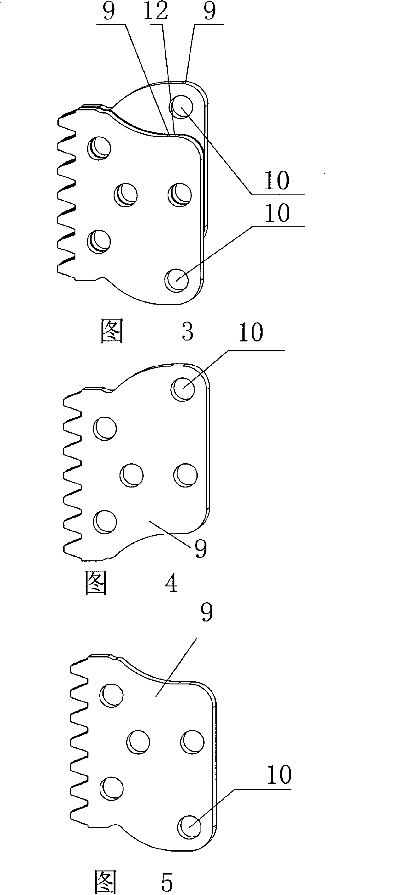
[0042] refer to figure 1- Fig. 5, the shapes of the upper and lower end surfaces of the tooth piece 9 in this embodiment mesh with each other, and the tooth block 8 is formed by the positive tooth piece formed by the forward setting of the tooth piece and the reverse setting formed by the tooth piece The counter gears are superimposed and fixedly connected. Adjacent tooth blocks have the same arrangement sequence of positive and negative gears. The positive gear has a convex part on the top, and the negative gear has a convex part on the bottom. , the positive tooth piece of the lower tooth block is hinged with the negative tooth piece of the adjacent upper tooth block. Other structures of this embodiment are the same as those of Embodiment 1.

[0043] In the processing process of this embodiment, it is necessary to determine two sets of molds for the spur gear and the reverse gear, respectively process the tooth structure of the gear through a punching machine, and then supe...

Embodiment 3

[0047] refer to figure 1 , figure 2 ,Image 6- Figure 8 , both ends of one side of the tooth piece 9 of the present embodiment are half-toothed. There is a mounting hole in the middle of the gear plate 9, and the mounting holes are symmetrically arranged with the center line of the upper part of the gear plate as the center line of the tooth shape. The center of the pin hole 10 is located at the edge of the upper tooth shape of the gear plate On the extension line of the line, the pin shaft 11 is installed on the pin shaft hole of the positive tooth plate of the tooth block below and the pin shaft hole of the anti tooth plate of the adjacent upper tooth block.

[0048] Other structures of this embodiment are the same as those of Embodiment 2.

[0049] In this embodiment, when superimposed, the mounting holes of the spur tooth and the adjacent anti-tooth are in one-to-one correspondence, and the pin installation holes of the spur tooth block correspond to the pin shaft inst...


PUM


Abstract

The invention discloses a stacked flexible rack-type lifting device, which comprises a fixed support, a driving device, a lifting support and a flexible rack used for jacking the lifting support. The upper end of the fixed support is provided with a gear which is connected with the driving device, the flexible rack is positioned in the fixed support which is provided with a guide rail, the upper part of the guide rail is vertical and provided with an arcuate extension section to the horizontal position, the flexible rack is provided with a pulley wheel matched with the guide rail and is a rigid chain formed by articulating a plurality of gear blocks, one side of the gear block takes the shape of teeth meshed with the gear, the adjoining teeth of adjacent gear blocks are jogged to form the complete tooth form, the adjacent gear blocks are articulated with each other at the side of no tooth form, and the gear block is formed by the superposition of lamellar toothed sheets. The invention provides the stacked flexible rack-type lifting device which reduces the process cycle, has good interchange capability and reduces the maintenance cost.

Description

technical field [0001] The invention relates to a lifting device. Background technique [0002] The use of lifting devices in all walks of life is relatively common, such as lifting platforms in heavy industries and storage industries, lifting platforms in the stage, and lifting orchestra pits. Commonly used lifting devices are: wire rope type, chain type, hydraulic type, rack type, spiral type, etc. [0003] For example, the patent number is 200420020574.7, and the invention name is a Chinese invention patent for a flexible rack type lifting device, which discloses a flexible rack type lifting device, including a fixed bracket fixed to the ground, a driving device, a lifting bracket, and a lifting bracket for jacking. The lifting mechanism of the lifting bracket, the lifting mechanism is installed in the fixed bracket, the lifting mechanism includes a rigid chain and a guide rail hinged by multi-section racks, the rigid chain and the The lifting bracket described above is...

Claims


Application Information

Patent Timeline
Patent Type & Authority Applications(China)
IPC IPC(8): B66F7/12B66F7/00B66F3/02B66F3/44
Inventor 丰华
Owner ZHEJIANG DAFENG IND
Why Eureka
Try Eureka