Rotary ultrasonic head based on machine tool attachment

An ultrasonic head and machine tool technology, applied in the direction of tool clamps, etc., can solve the problems of speed limit, poor interchangeability, wear or damage, etc., to meet the needs of high-power processing, good versatility and interchangeability, and improved induction efficiency. Effect

Active Publication Date: 2011-08-17
TIANJIN UNIV
View PDF10 Cites 29 Cited by
  • Summary
  • Abstract
  • Description
  • Claims
  • Application Information

AI Technical Summary

Problems solved by technology

Yet present ultrasonic machining device has many defects, as: the patent No. is 200310105459.X (authorized announcement number is CN100364673C), and its authorized announcement date is disclosed in the Chinese invention patent on January 30, 2008 " a kind of high-efficiency ultrasonic Processing Equipment", the machine tool can no longer perform other types of processing except for ultrasonic processing; another example: the patent application number is 200910226156.0 (publication number is CN101704219A), and its publication date is May 12, 2010 in China The invention patent application discloses "A Kind of Ultrasonic Processing Equipment". Although this equipment can realize ultrasonic processing and non-ultrasonic processing such as turning and grinding on the same machine tool, due to its complex structure and poor interchangeability, it cannot be processed by simple Ultrasonic processing can be realized on any ordinary CNC machine tool, therefore, it affects the promotion and use of ultrasonic processing
[0003] At present, most ultrasonic processing devices use the power supply method of the brush, in which the slip ring is always in contact with the power supply brush, so the wear or damage is serious. Therefore, in addition to the frequent replacement of the power supply brush, the stability and reliability cannot be guaranteed. I

Method used


Image

  • Rotary ultrasonic head based on machine tool attachment
  • Rotary ultrasonic head based on machine tool attachment
  • Rotary ultrasonic head based on machine tool attachment

Examples


Embodiment 1

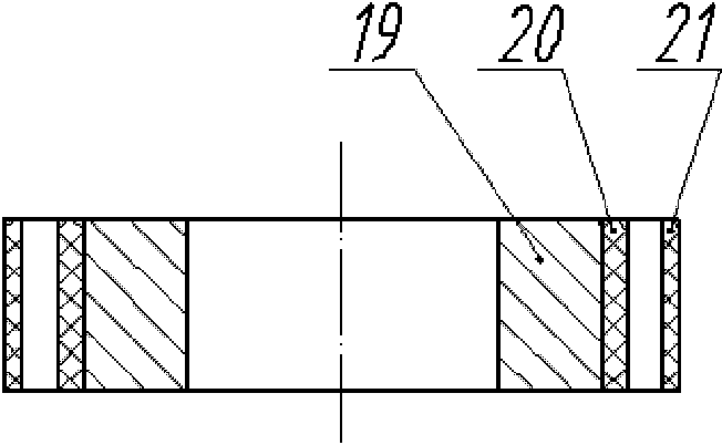
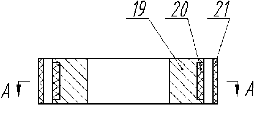
[0087] Figure 11 It shows the structure of Embodiment 1 of a rotary ultrasonic head based on the machine tool attachment of the present invention. The main components include an ultrasonic vibration working device, a non-contact collector ring, a main shaft 17, a tool handle 16, a support shell 12, and a shift fork 13. The first bearing 11, the second bearing 14, the main side insulating cage 22 of the collector ring, and the secondary side insulating cage 23 of the collector ring.

[0088] Some accessories are not shown among the figure, these accessories can be changed under the situation that the gist of the present invention remains unchanged.

[0089] One end of the main shaft 17 has an inner cavity D, and the inner cavity D is coaxial with the main shaft 17. Tool handle 16 is installed, the rotation axes of ultrasonic vibration working device (18, 9, 8, 7, 6), main shaft 17 and tool handle 16 are on the same straight line, and tool handle 16 is installed on the machine...

Embodiment 2

[0097] like Figure 12 Shown is the structure of Embodiment 2 of a rotary ultrasonic head based on machine tool attachment of the present invention, which is the same as Figure 11 The same parts of the illustrated embodiments will not be repeated, and only the differences will be described.

[0098] In the second example, the Figure 11 The split tool holder 16 and the main shaft 17 in the Figure 12The one-piece tool holder main shaft 24 shown in , that is, cancel the connecting part between the two under the premise that the respective functions of the tool holder and the main shaft remain unchanged, and manufacture the two as a whole. The one-piece tool holder main shaft 24 is due to the The handle and the main shaft are a whole and cannot be disassembled, that is, a rotating ultrasonic head corresponds to a certain type of tool handle, and can only be installed on the machine tool spindle that matches the type of tool handle. The interchangeability of the integrated typ...

Embodiment 3

[0100] like Figure 13 Shown is the structure of Embodiment 3 of a rotary ultrasonic head based on machine tool attachment of the present invention, which is the same as Figure 11 The same parts of the illustrated embodiments will not be repeated, and only the differences will be described.

[0101] Figure 13 The third embodiment shown does not have Figure 11 The first bearing 11 and the second bearing 14, the shift fork 13 and the accessories equipped for installing the bearings in the shown embodiment one, but the end of the support shell 12 close to the tool handle is directly fixedly connected with the machine tool bed, in this Under the premise that the purpose of the invention remains unchanged, the connection method can be that a magnetic seat (not shown in the figure) is set near the end of the support shell 12 near the handle of a knife, or use other connection methods. use Figure 13 In the third embodiment shown, the requirement for the coaxiality of the supp...


PUM


Abstract

The invention discloses a rotary ultrasonic head based on machine tool attachment. The rotary ultrasonic head comprises an ultrasonic vibration operating device, a non-contact collector ring, a main shaft, a knife handle and a supporting shell, wherein, the knife handle with a standard model is adopted; the ultrasonic vibration operating device is connected with one end of the main shaft; the knife handle is connected with the other end of the main shaft; rotation axes of the ultrasonic vibration operating device, the knife handle and the main shaft are positioned on the same straight line; and the non-contact collector ring is arranged between the main shaft and the supporting shell, and an ultrasonic vibration signal is transmitted to the ultrasonic vibration operating device in a non-contact manner through the non-contact collector ring. The rotary ultrasonic head has the following outstanding advantages: (1) complete machine tool attachment as well as generality and interchangeability of an ultrasonic machining device are realized; and (2) the induction efficiency of a brushless non-contact power supply system of the ultrasonic machining device is improved, the efficient energy transfer is realized, and the energy loss is reduced.

Description

technical field [0001] The invention relates to a rotating ultrasonic machining spindle device, in particular to a rotating ultrasonic machining spindle device which seeks to realize machine tool attachment and brushless non-contact power supply. Background technique [0002] Ultrasonic machining is often used in the processing of hard and brittle materials, which can effectively improve the surface quality of workpieces, reduce surface roughness and improve machining accuracy. Yet present ultrasonic machining device has many defects, as: the patent No. is 200310105459.X (authorized announcement number is CN100364673C), and its authorized announcement date is disclosed in the Chinese invention patent on January 30, 2008 " a kind of high-efficiency ultrasonic Processing Equipment", the machine tool can no longer perform other types of processing except for ultrasonic processing; another example: the patent application number is 200910226156.0 (publication number is CN10170421...

Claims


Application Information

Patent Timeline
IPC IPC(8): B23B37/00B23B29/12
Inventor 林彬刘礼平朱学明
Owner TIANJIN UNIV
Why Eureka
Try Eureka