Fork operation monitoring system of forklift

An operation monitoring system and fork technology, which is applied in the field of human-computer information interaction of reach-type forklifts, can solve problems such as impacting forklifts, bruising goods and shelves, and falling goods, achieving good versatility and interchangeability, and avoiding accidental collisions , easy to promote the effect

Active Publication Date: 2015-11-25
WUHU RUICHUANG FORKELEVATOR
View PDF8 Cites 7 Cited by
  • Summary
  • Abstract
  • Description
  • Claims
  • Application Information

AI Technical Summary

Problems solved by technology

[0002] Forklifts are commonly used mechanical equipment in production operations. At present, there are the following problems in the use of forklifts. Forklifts, especially high-position forklifts, when the driver picks up and stacks goods, it is difficult to see clearly because the sight is blocked by the goods and the mast. The position of the goods relative to the shelf causes low efficiency in handling or stacking goods, and even dangerous situations such as bumping the goods and shelves, and falling goods
[0003] In response to this problem, a few manufacturers have added fork monitoring devices, or fork imaging devices, or fork monitors, etc. to forklifts. Connected by cables, there are video signal lines and camera power supply lines. However, such a monitoring system will frequently change the position of the camera relative to the display due to the frequent lifting of the fork of the forklift, and the connection cable between the camera and the display will also change accordingly. Because of the movement, the length often needs to be changed. Such a monitoring system undoubtedly increases the difficulty of handling the wiring harness. At the same time, it cannot guarantee the connection reliability of the wiring harness, which affects the normal operation of the forklift.

Method used


Image

  • Fork operation monitoring system of forklift
  • Fork operation monitoring system of forklift
  • Fork operation monitoring system of forklift

Examples


Embodiment approach

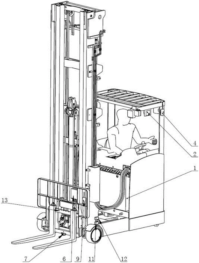
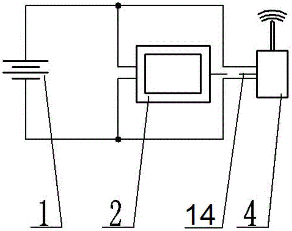
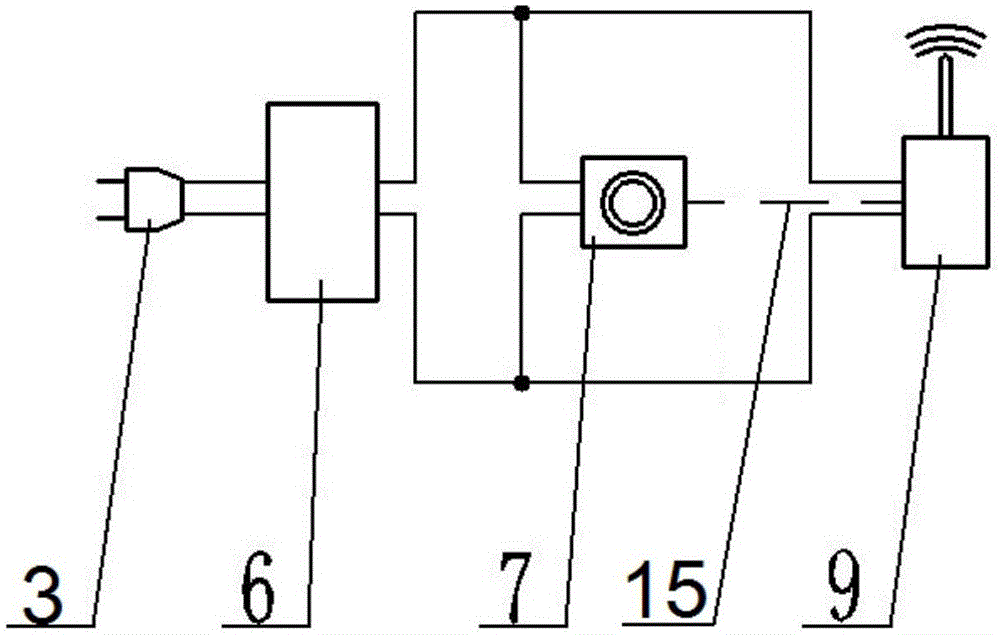
[0027] As shown in Figure 2(a) and Figure 2(b), the system power supply 6 is a rechargeable battery, which can store a certain amount of electricity, and the output terminal of the rechargeable battery can output current at a certain voltage, and the output terminal is connected to the camera 7 and the wireless transmitter respectively. The device 9 is connected by a cable. The rechargeable battery can supply power to the camera 7 and the wireless transmitter 9, and generally it is advisable to supply them with continuous work for 10-12 hours, for example, the output voltage specification is 12V and the capacity is 240Ah. The rechargeable battery is provided with a charging plug 3, and in the case of insufficient power, when the forklift body power supply 1 is charged, the rechargeable battery is connected to the mains power supply by the charging plug 3 for charging. When the rechargeable battery is supplied with charging current at its input terminal, there is a protection c...


PUM


Abstract

The invention discloses a fork operation monitoring system of a forklift. A display is arranged in a cab of the forklift. A camera is arranged on a forklift fork unit. A wireless receiver is arranged on the display. A wireless transmitter is arranged on the camera. The camera transmits collected signals to the wireless receiver through the wireless transmitter. The wireless receiver transmits the received signals to the display. According to the scheme, the technologies are combined and applied, and the fork monitoring problem of an existing forklift is solved. By means of the scheme, a driver can observe the conditions of goods and a fork at any time through videos displayed by the display, stacked goods at different heights in different positions can be forked and taken conveniently, alignment with a goods rack is facilitated, and accidental collision of the goods with the fork is avoided; related cables will not be worn, the service life is long, and extra risks are avoided; and the whole system is convenient to arrange, good in universality and interchangeability and easy to popularize, and the increase of extra risks is avoided.

Description

technical field [0001] The invention relates to the field of human-computer information interaction of a reach-type forklift. Background technique [0002] Forklifts are commonly used mechanical equipment in production operations. At present, there are the following problems in the use of forklifts. Forklifts, especially high-position forklifts, when the driver picks up and stacks goods, it is difficult to see clearly because the sight is blocked by the goods and the mast. The position of the goods relative to the shelf results in low efficiency in handling or stacking goods, and even dangerous situations such as bruising the goods and shelves, and falling goods. [0003] In response to this problem, a few manufacturers have added fork monitoring devices, or fork imaging devices, or fork monitors, etc. to forklifts. Connected by cables, there are video signal lines and camera power supply lines. However, such a monitoring system will frequently change the position of the ca...

Claims


Application Information

Patent Timeline
Patent Type & Authority Applications(China)
IPC IPC(8): B66F9/075B66F17/00
CPCB66F9/075B66F17/00
Inventor 陈晓宇孟凡冬石春华
Owner WUHU RUICHUANG FORKELEVATOR
Why Eureka
Try Eureka