Image tracking method and system thereof

An image tracking and target image technology, applied in the field of image tracking, can solve the problems of loss of spatial position information, tracking failure, etc.

Active Publication Date: 2007-09-19
中星智能系统技术有限公司
View PDF0 Cites 10 Cited by
  • Summary
  • Abstract
  • Description
  • Claims
  • Application Information

AI Technical Summary

Problems solved by technology

[0003] In the target tracking algorithm based on histogram matching, there are many implementation methods in the prior art, such as the Meanshift target tracking algorithm, and the target tracking algorithm based on global search, etc., but in these algorithms, when calculating the histogr

Method used


Image

  • Image tracking method and system thereof
  • Image tracking method and system thereof
  • Image tracking method and system thereof

Examples


Embodiment 1

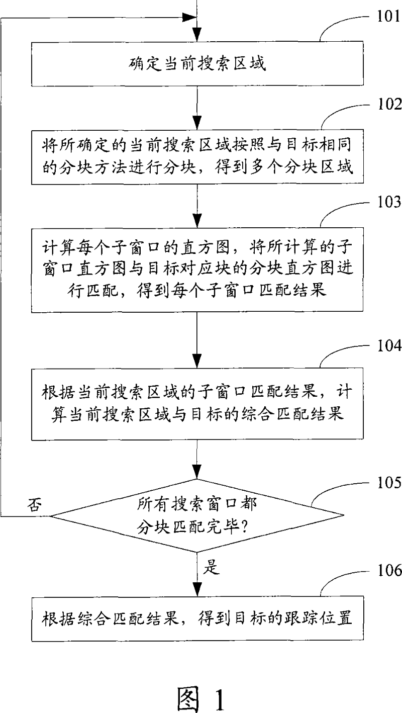
[0083] FIG. 1 is a flowchart of an image tracking method in Embodiment 1 of the present invention. As shown in Figure 1, the process includes the following steps:

[0084] Step 101, determine the current search window.

[0085] In this step, the current search window may be determined according to the selection method in the prior art, or other methods may be used to determine the current search window.

[0086] For example: the tracking area can be set in the current frame image in advance, and the current search window can be determined in the entire tracking area. Alternatively, the current search window may also be determined among several preset search windows.

[0087] In this embodiment, if a tracking area is set in the current frame image, there are multiple methods for setting the tracking area. One of them may be: first obtain the predicted position of the target through position prediction, and then set the entire tracking area of ​​the target according to the ma...

Embodiment 2

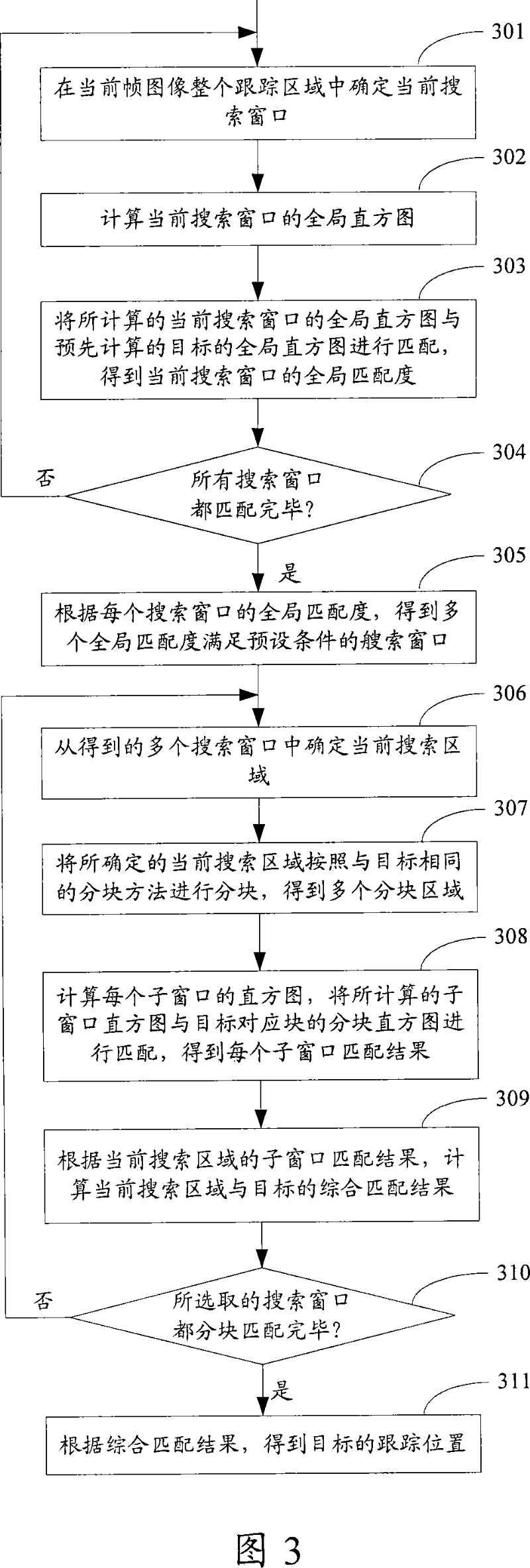
[0146] FIG. 3 is a flow chart of the image tracking method in Embodiment 2 of the present invention. As shown in Figure 3, the process includes the following steps:

[0147] Step 301, determine the current search window in the entire tracking area of ​​the current frame image.

[0148] In this embodiment, the tracking area can be set in the current frame image, and the method for determining the current search window in the entire tracking area in this step can be consistent with the description in step 101 shown in FIG. 1 .

[0149] Step 302, calculate the global histogram of the current search window.

[0150] In this step, the method for calculating the global histogram is consistent with the histogram calculation method described in step 103 shown in FIG. 1 . And the global histogram here can be a color histogram, or a color histogram combined with a gradient direction histogram, or a gradient direction histogram, etc.

[0151] Step 303, matching the calculated global h...

Embodiment 3

[0180] The image tracking method in this embodiment may be consistent with the image tracking method in Embodiment 1, and may also be consistent with the image tracking method in Embodiment 2. The difference is:

[0181] In order to reduce the number of calculations of the histogram, improve the operation speed, and ensure the real-time performance of the tracking, in this embodiment, the histogram (including the block histogram and the global histogram) described in the first embodiment and the second embodiment is adopted The method shown in Fig. 5 is calculated, and Fig. 5 is the flow chart of the histogram calculation method in the third embodiment of the present invention, and this process comprises the following steps:

[0182] Step 501, pre-calculate the area integral histogram of the entire tracking area.

[0183] Wherein, when calculating the area integral histogram of the entire tracking area, the histograms of all areas in the entire tracking area with a preset cor...


PUM


Abstract

The invention discloses an image tracking method comprising partitioning a target image and obtaining a block histogram for each block of the target image by calculation. In the method, every search windows are partitioned according to a partitioning manner corresponding to the target image, respectively, to obtain sub-windows of each search window; a histogram of each sub-window is calculated, and the obtained histogram of each sub-window is matched with the partitioning histogram of a corresponding block of the target image so as to obtain a matching degree of each sub-window; a matching result of each search window is obtained according to the matching degree of each sub-window in each search window, and tracking position of the target image is determined by the matching results. In addition, the invention discloses an image tracking system. The method and system disclosed in the invention avoid a circumstance of failed tracking induced by losting space position information of respective pixels during a statistical process, and ensures tracking effect.

Description

technical field [0001] The invention relates to image tracking technology, in particular to an image tracking method and system. Background technique [0002] In the current image tracking technology, the target tracking algorithm based on histogram matching is usually used to track the target, that is, to search for the best matching corresponding target in the area where the target may appear in a new frame of image, as the new position of the target. The specific process includes: determining each search window in the tracking area, matching the histogram of each search window with the standard histogram of the target, and taking the best matching search window as the new position of the target. Among them, considering that the size of the target in each frame of image may be different due to the distance movement of the target during the shooting process of each frame of image, that is, the scale of the target in each frame of image may be different, therefore, in In ad...

Claims


Application Information

Patent Timeline
IPC IPC(8): G06T7/20
Inventor 曾志王耀辉
Owner 中星智能系统技术有限公司
Why Eureka
Try Eureka