Image tracking method and system thereof
An image tracking and target image technology, applied in the field of image tracking, can solve problems such as tracking failure and loss of spatial position information
- Summary
- Abstract
- Description
- Claims
- Application Information
AI Technical Summary
Problems solved by technology
Method used
Image
Examples
Embodiment 1
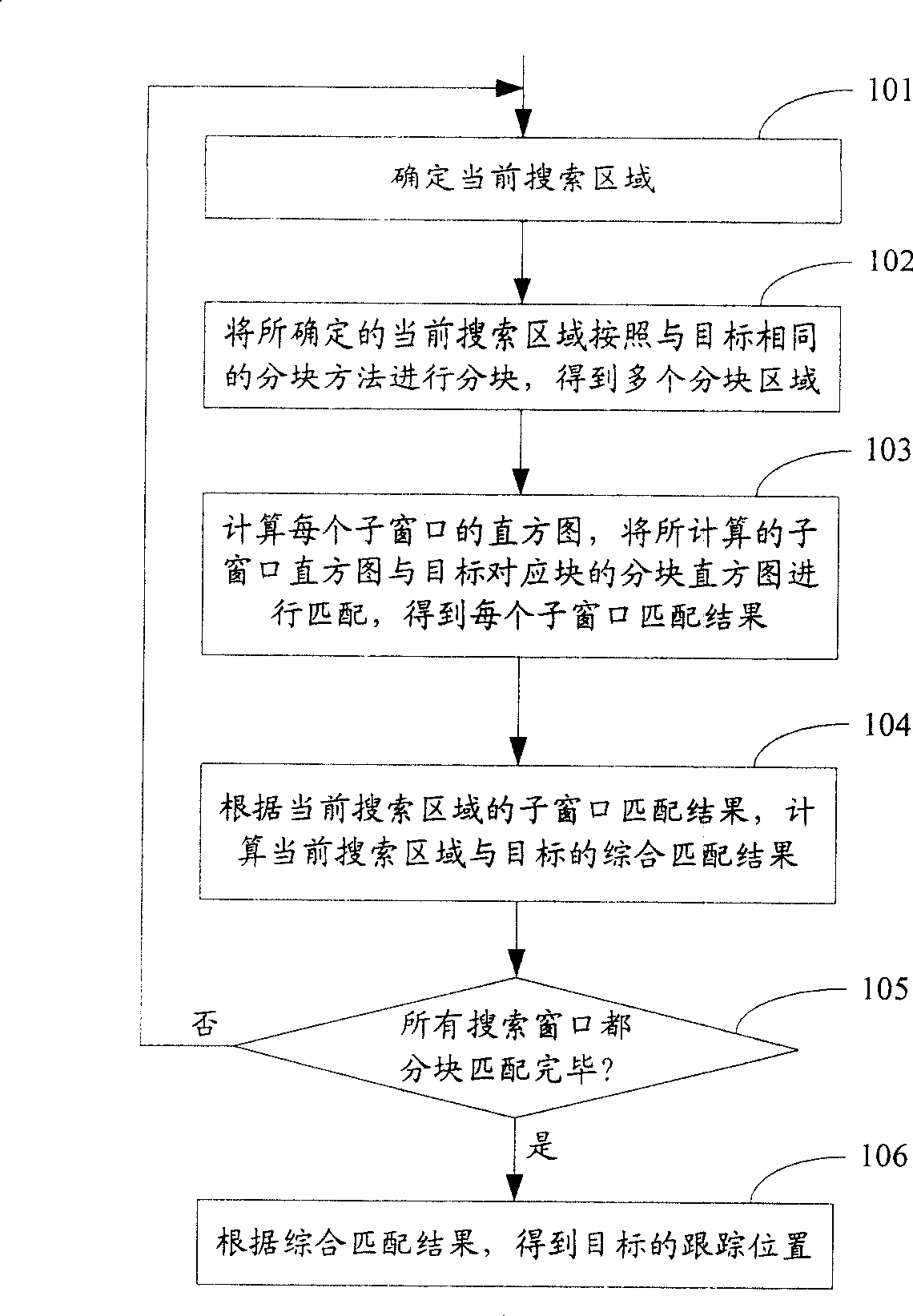
[0083] figure 1 It is a flow chart of the image tracking method in Embodiment 1 of the present invention. Such as figure 1 As shown, the process includes the following steps:
[0084] Step 101, determine the current search window.
[0085] In this step, the current search window may be determined according to the selection method in the prior art, or other methods may be used to determine the current search window.
[0086] For example: the tracking area can be set in the current frame image in advance, and the current search window can be determined in the entire tracking area. Alternatively, the current search window may also be determined among several preset search windows.
[0087] In this embodiment, if a tracking area is set in the current frame image, there are multiple methods for setting the tracking area. One of them may be: first obtain the predicted position of the target through position prediction, and then set the entire tracking area of the target accor...
Embodiment 2
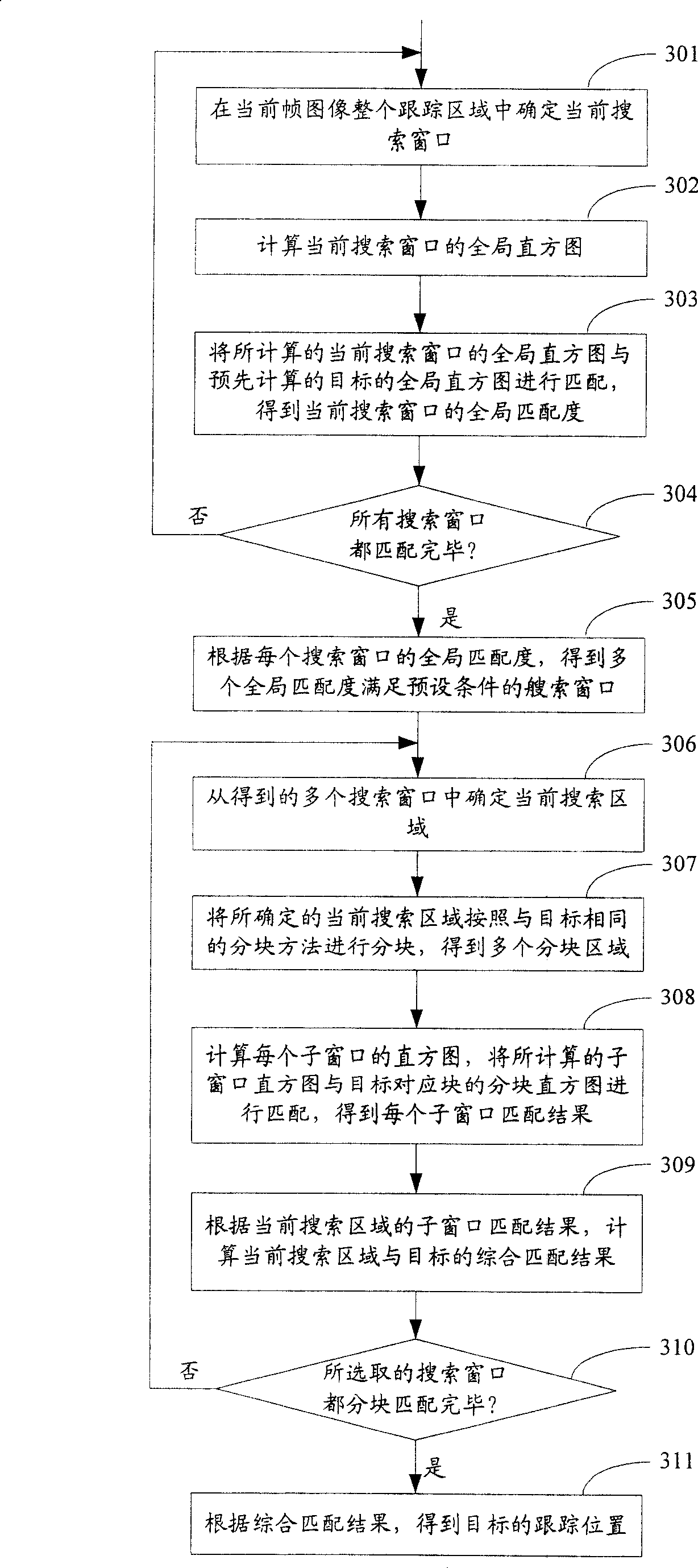
[0145] image 3 It is a flow chart of the image tracking method in Embodiment 2 of the present invention. Such as image 3 As shown, the process includes the following steps:
[0146] Step 301, determine the current search window in the entire tracking area of the current frame image.
[0147] In this embodiment, the tracking area can be set in the current frame image, then the method of determining the current search window in the entire tracking area in this step can be compared with figure 1 The description in step 101 shown is consistent.
[0148] Step 302, calculate the global histogram of the current search window.
[0149] In this step, the method of calculating the global histogram is the same as figure 1 The method for calculating the histogram described in step 103 is the same. And the global histogram here can be a color histogram, or a color histogram combined with a gradient direction histogram, or a gradient direction histogram, etc.
[0150] Step 303, m...
Embodiment 3
[0179] The image tracking method in this embodiment may be consistent with the image tracking method in Embodiment 1, and may also be consistent with the image tracking method in Embodiment 2. The difference is:
[0180] In order to reduce the number of calculations of the histogram, improve the operation speed, and ensure the real-time performance of the tracking, in this embodiment, the histogram (including the block histogram and the global histogram) described in the first embodiment and the second embodiment is adopted Figure 5 The method shown is calculated, Figure 5 It is a flow chart of the histogram calculation method in Embodiment 3 of the present invention, and the process includes the following steps:
[0181] Step 501, pre-calculate the area integral histogram of the entire tracking area.
[0182] Wherein, when calculating the area integral histogram of the entire tracking area, the histograms of all areas in the entire tracking area with a preset corner of th...
PUM
 Abstract
Description
Claims
Application Information
 - R&D
- Intellectual Property
- Life Sciences
- Materials
- Tech Scout
- Unparalleled Data Quality
- Higher Quality Content
- 60% Fewer Hallucinations
Browse by: Latest US Patents, China's latest patents, Technical Efficacy Thesaurus, Application Domain, Technology Topic, Popular Technical Reports.
© 2025 PatSnap. All rights reserved.Legal|Privacy policy|Modern Slavery Act Transparency Statement|Sitemap|About US| Contact US: help@patsnap.com


