Image tracking method and system thereof
A technology of image tracking and tracking area, which is applied in the field of image tracking and can solve the problems of poor real-time tracking and large amount of calculation
- Summary
- Abstract
- Description
- Claims
- Application Information
AI Technical Summary
Problems solved by technology
Method used
Image
Examples
Embodiment 1
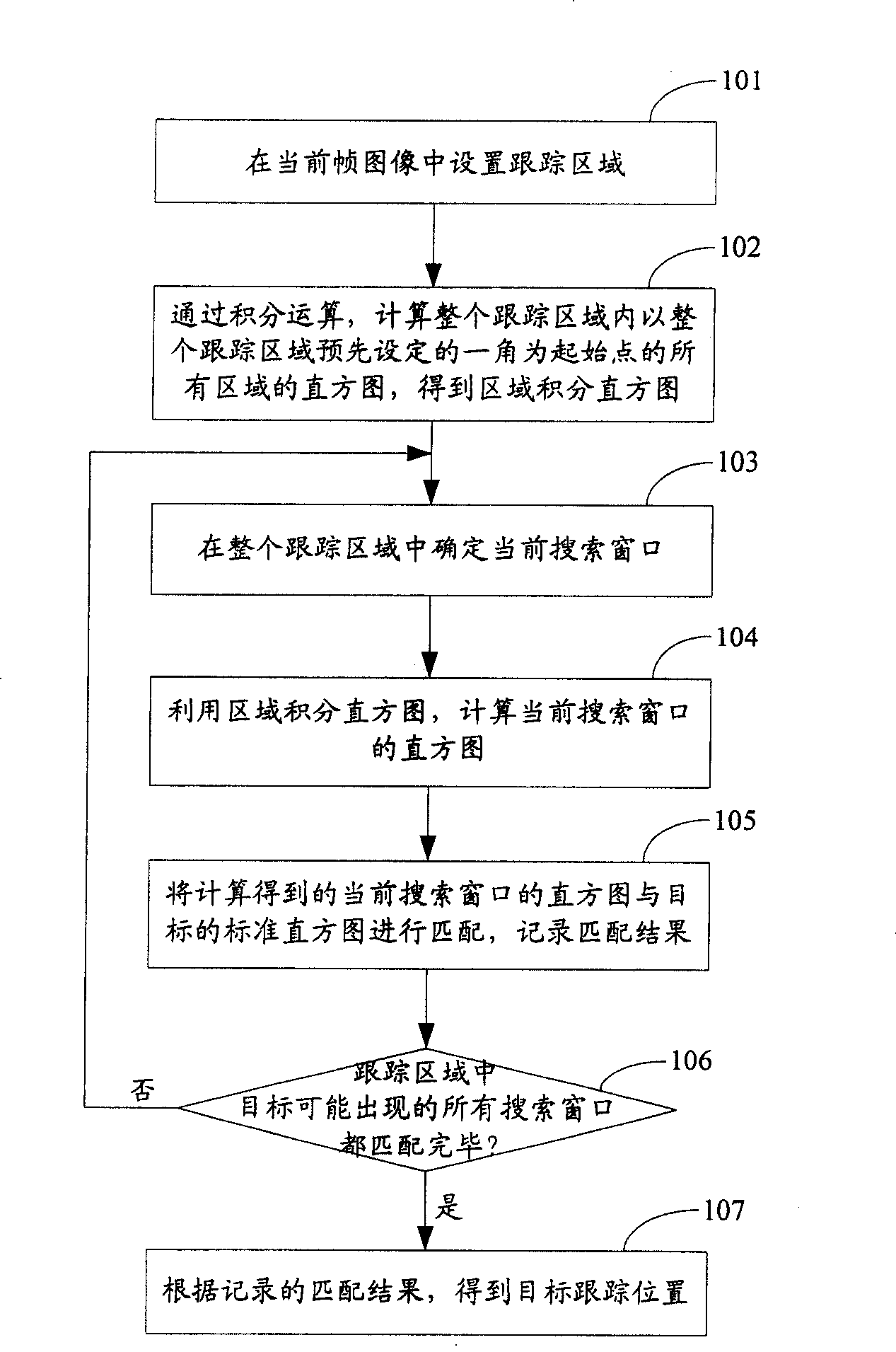
[0084] see figure 1 , figure 1 It is a flow chart of the image tracking method in Embodiment 1 of the present invention. Such as figure 1 As shown, the process includes the following steps:
[0085] Step 101, setting a tracking area in the current frame image.
[0086] In this step, there are many ways to set the tracking area. One of them may be: first obtain the predicted position of the target through position prediction, and then set the entire tracking area of the target according to the maximum moving speed of the target based on the predicted position of the target.
[0087] For example: the following position prediction method can be used to obtain the predicted position of the target:
[0088] If the tracked target’s position at time t is (x t ,y t ), at time t-Δ t The position is (x t-1 ,y t-1 ), then the velocity of the current target can be simply estimated as v x =(x t -x t-1 ) / Δ t , v y =(y t -y t-1 ) / Δ t .
[0089] Considering the irregular ...
Embodiment 2
[0165] The image tracking method in this embodiment is roughly the same as the image tracking method in Embodiment 1, the difference is that:
[0166] exist figure 1 In step 102 of the shown method flow, the first embodiment uses a color histogram, but in this case, when there is an object with a color similar to the target in the tracking area, since the color histogram is only a description of the color , so it is easy to be interfered by objects with similar colors to the target, making the tracking inaccurate. Therefore, in step 102 of this embodiment, on the basis of using the color histogram, another histogram is added, that is, the gradient direction histogram picture.
[0167] The gradient direction histogram refers to: determine the angle interval of the gradient direction according to the number of histogram groups; calculate the angle interval to which the gradient direction of each pixel belongs, and obtain the histogram group to which the pixel belongs. The spec...
Embodiment 3
[0181] The image tracking method in this embodiment may adopt steps 101 to 106 in Embodiment 1, or may adopt Steps 101 to 106 in Embodiment 2. The difference between this embodiment and embodiment one or embodiment two is:
[0182] The first point: In order to reflect the edge characteristics and spatial position characteristics of the target, the target is divided into blocks according to the preset number of blocks in advance, and the block histogram of the target is calculated. Then the standard histogram of the target also includes the block histogram.
[0183] Wherein, the standard histogram of the target in Embodiment 1 and Embodiment 2 is the global histogram of the target, and the standard histogram of the target in this embodiment includes not only the global histogram of the target, but also the block histogram of the target. Assuming that the target is divided into M×N blocks, and the histogram includes the histogram and gradient direction histogram of each color c...
PUM
 Abstract
Description
Claims
Application Information
 - R&D
- Intellectual Property
- Life Sciences
- Materials
- Tech Scout
- Unparalleled Data Quality
- Higher Quality Content
- 60% Fewer Hallucinations
Browse by: Latest US Patents, China's latest patents, Technical Efficacy Thesaurus, Application Domain, Technology Topic, Popular Technical Reports.
© 2025 PatSnap. All rights reserved.Legal|Privacy policy|Modern Slavery Act Transparency Statement|Sitemap|About US| Contact US: help@patsnap.com


