

Zoom lens
一种变焦透镜、透镜的技术,应用在变焦透镜领域,能够解决降低透过率、高折射率、第1透镜组大等问题,达到抑制透过率的降低、良好光学性能、容易薄型化的效果
- Summary
- Abstract
- Description
- Claims
- Application Information
AI Technical Summary
Problems solved by technology
Method used
Image

Examples
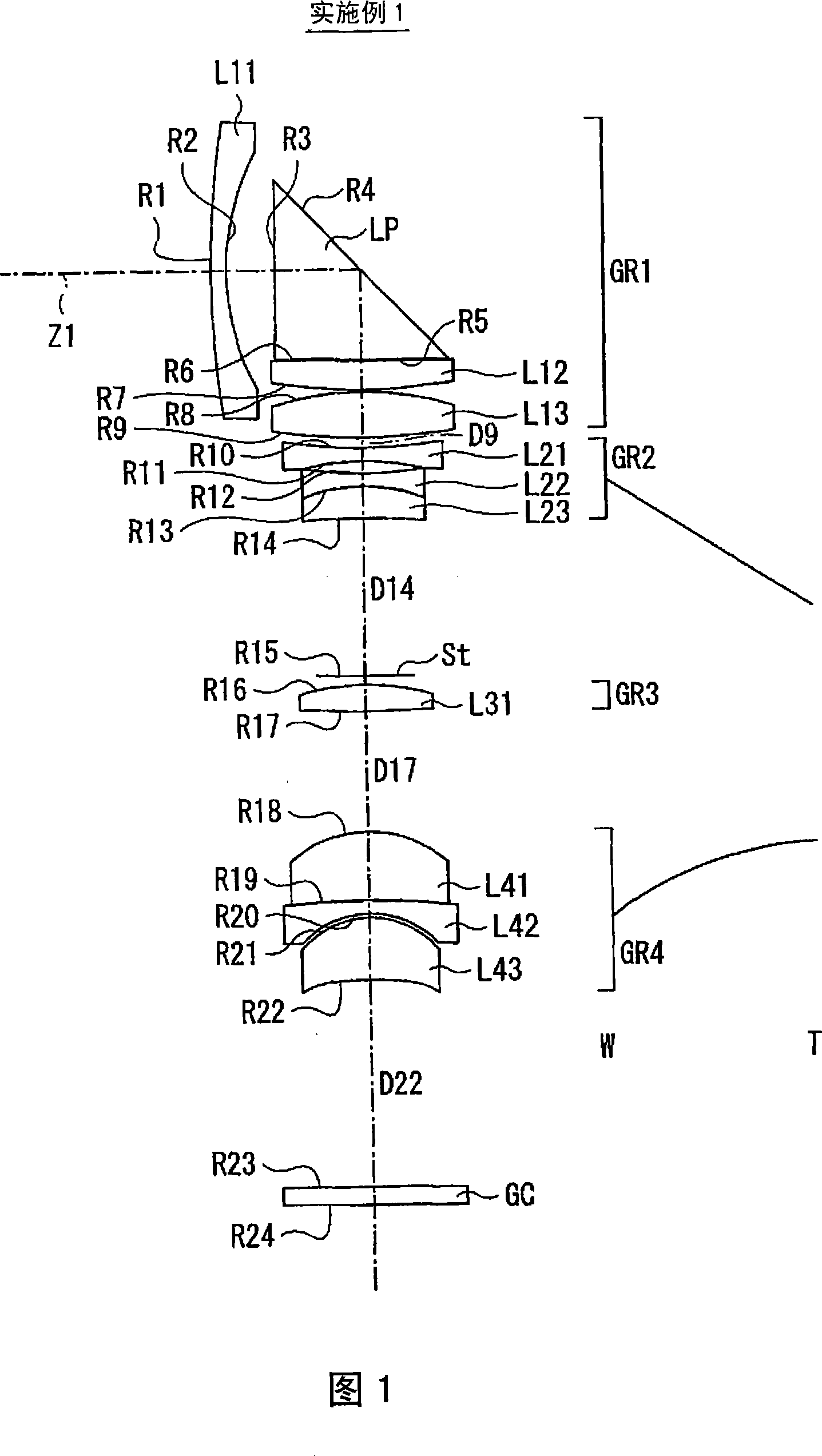
Embodiment 1
[0072] In the zoom lens of Example 1, since the second lens group GR2 and the fourth lens group GR4 move on the optical axis as the magnification is changed, the values of the surface intervals D9, D14, D17, and D22 before and after these groups are variable. . FIG. 4(B) shows that the values at the wide-angle end and the telephoto end are shown as data when these plane intervals D9 , D14 , D17 , and D22 are variable in magnification.
[0073] In the lens data of FIG. 4(A), the symbol "*" attached to the left side of the surface number indicates that the lens surface has an aspherical shape. In the zoom lens of Example 1, the two surfaces S8 and S9 of the third lens L13 in the first lens group GR1, the two surfaces S16 and S17 of the lens L31 in the three-lens group GR3, and the lens L43 in the fourth lens group GR4 Both surfaces S21 and S22 are formed in an aspherical shape. In the basic lens data of FIG. 4(A), as the radii of curvature of these aspherical surfaces, num...
PUM
 Abstract
Description
Claims
Application Information