Supercharge Your Innovation With Domain-Expert AI Agents!

Displacement measurement systems lithographic apparatus and device manufacturing method

一种位移测量、测量系统的技术,应用在制造器件领域,能够解决增加成本、占用、降低光刻装置产量等问题

Active Publication Date: 2007-09-26
ASML NETHERLANDS BV
View PDF0 Cites 11 Cited by
  • Summary
  • Abstract
  • Description
  • Claims
  • Application Information

AI Technical Summary

Problems solved by technology

However, minimizing such disturbances, e.g. by introducing delays to reduce air turbulence and / or stabilize air temperature within desired values, also reduces the throughput of the lithographic apparatus, thus increasing the use of the Device cost
[0005] Furthermore, any measurement system can only occupy a limited volume of space inside the lithography setup

Method used


Image

  • Displacement measurement systems lithographic apparatus and device manufacturing method
  • Displacement measurement systems lithographic apparatus and device manufacturing method
  • Displacement measurement systems lithographic apparatus and device manufacturing method

Examples


Embodiment Construction

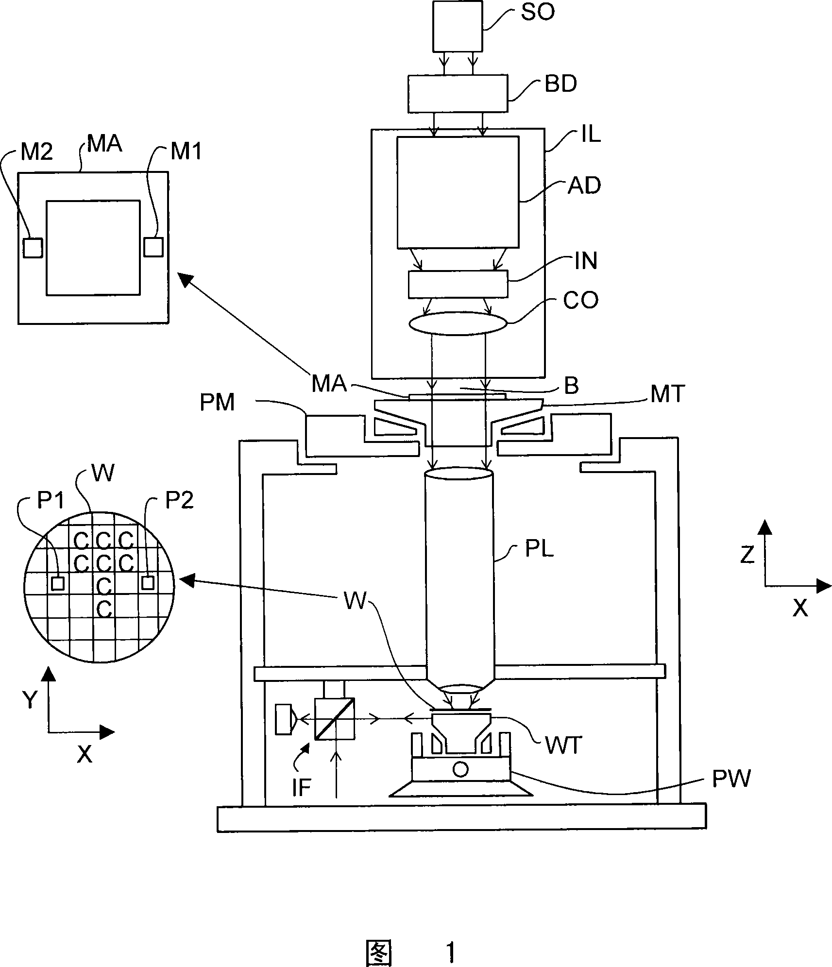
[0026] Fig. 1 schematically shows a lithographic apparatus according to an embodiment of the present invention. The apparatus comprises: an illumination system (illuminator) IL configured to condition a radiation beam B (e.g. UV radiation or EUV radiation); a support structure (e.g. a mask table) MT configured to support a patterning member (e.g. a mask) MA and is connected with a first positioner PM configured to precisely position the patterning member according to certain parameters; a substrate table (such as a wafer stage) WT configured to hold a substrate (such as a resist-coated wafer) W and is connected to a second positioner PW configured to precisely position the substrate according to certain parameters; and a projection system (such as a refractive projection lens system) PS configured to assign A pattern of radiation beam B is projected onto a target portion C of substrate W (eg, comprising one or more dies).

[0027] The illumination system may include various t...


PUM


Abstract

A displacement measurement system configured to provide measurement of the relative displacement of two components in six degrees of freedom with improved consistency and without requiring excessive space.

Description

technical field [0001] The invention relates to a displacement measurement system, a lithographic apparatus and a method for fabricating a device. Background technique [0002] A lithographic apparatus is a device that applies a desired pattern to a substrate, usually to a target portion of the substrate. A lithographic apparatus may be used, for example, in the manufacture of integrated circuits (ICs). In this case, a patterning device, which may also be referred to as a mask or reticle, may be used to create a circuit pattern formed on a single layer of the IC. The pattern may be transferred onto a target portion (eg comprising a portion, one or more dies) of a substrate (eg a silicon wafer). This transfer of the pattern is usually performed by imaging onto a layer of radiation sensitive material (resist) on the substrate. In general, a single substrate contains a grid of adjacent target portions that are patterned sequentially. Known lithographic apparatuses include s...

Claims


Application Information

Patent Timeline
Patent Type & Authority Applications(China)
IPC IPC(8): G03F7/20G01B11/00H01L21/027
CPCG01D5/38G03F7/70775G03F7/70483G03F7/7085G03F7/70883H01L21/67259
Inventor R·G·克拉维E·R·鲁普斯特拉E·A·F·范德帕斯奇
Owner ASML NETHERLANDS BV
Features
  • R&D
  • Intellectual Property
  • Life Sciences
  • Materials
  • Tech Scout
  • Unparalleled Data Quality
  • Higher Quality Content
  • 60% Fewer Hallucinations
Learn More