Drive method of plasma display device

A technology of plasma display and driving method, which is applied to static indicators, instruments, identification devices, etc., and can solve problems such as poor discharge and deterioration of jitter characteristics

Inactive Publication Date: 2007-09-26
LG ELECTRONICS(NANJING) PLASMA CO LTD
View PDF0 Cites 0 Cited by
  • Summary
  • Abstract
  • Description
  • Claims
  • Application Information

AI Technical Summary

Problems solved by technology

As a result, there are problems of poor discharge or deterioration of jitter characteristics.

Method used


Image

  • Drive method of plasma display device
  • Drive method of plasma display device
  • Drive method of plasma display device

Examples


Embodiment Construction

[0017] Hereinafter, embodiments of the present invention will be described in detail with reference to the accompanying drawings.

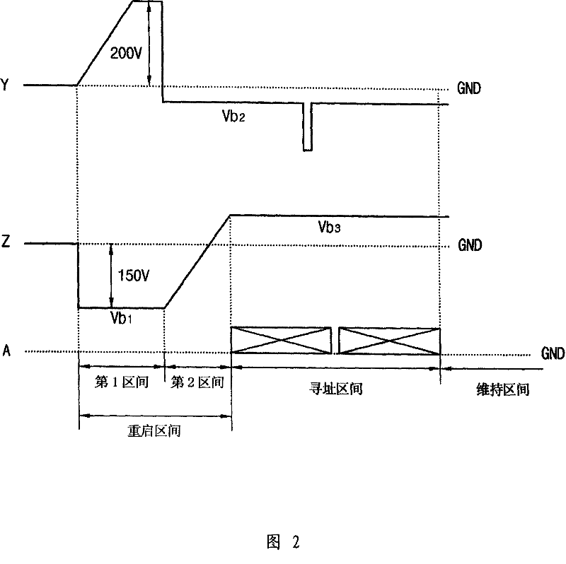
[0018] Fig. 2 is a waveform diagram of the driving of the plasma display of the present invention.

[0019] As shown in FIG. 2 , in the first interval of the reset interval, an up-ramp pulse with a specific slope higher than the ground voltage level is input to the Y electrode, and a negative first bias voltage (Vb1) is input to the Z electrode. At the same time, in the second interval of the reset interval, a negative second bias voltage (Vb2) is input to the Y electrode, and a third bias voltage is input to the Z electrode that is increased by a certain slope from the first bias voltage (Vb1) to reach the positive polarity. Pulse of voltage (Vb3).

[0020] At this time, in the first interval and the second interval, the voltage input to the X electrode is the ground voltage.

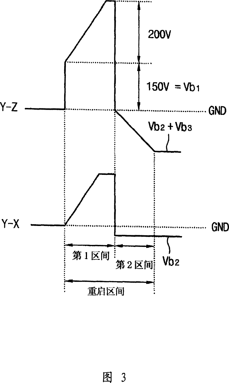
[0021] FIG. 3 shows the voltage difference formed between the Y ele...


PUM


Abstract

This invention relates to one plasma display drive method, which comprises the following steps: on first area, adding special inclination upper impulse to Y electrode input the comparison earth connection voltage degree and inputting first bias voltage to Z electrode input cathode with first bias voltage; in second area, inputting cathode second bias voltage to Y electrode and adding special inclination to Z electrode with first bias voltage to achieve third bias voltage impulse; inputting earth connection voltage to X electrode in first and second areas.

Description

technical field [0001] The invention relates to a plasma display. In particular, it relates to a driving method of a plasma display. Background technique [0002] FIG. 1 is a waveform diagram for driving a plasma display in the prior art. As shown in Figure 1, it includes restart interval, address interval and maintenance interval. At the same time, the restart interval includes an ascending interval and a descending interval. [0003] In the rising interval, a high-voltage upward slope pulse is input to the Y electrode, causing surface discharge between the Y electrode and the Z electrode and a large amount of discharge between the Y electrode and the X electrode, and forming a lot of wall charges at the same time. [0004] In the falling interval, a down-ramp pulse is input to the Y electrode, and the wall charges formed on the electrodes are eliminated to a certain extent, and uniform wall charges are formed in each discharge cell. [0005] In the address period, a sc...

Claims


Application Information

Patent Timeline
Patent Type & Authority Applications(China)
IPC IPC(8): G09G3/28G09G3/20H01J17/49G09F9/313G09G3/288
Inventor 郑真熙
Owner LG ELECTRONICS(NANJING) PLASMA CO LTD
Why Eureka
Try Eureka