
Driving apparatus

A driving device and driven technology, applied in the direction of installation, generator/motor, piezoelectric effect/electrostrictive or magnetostrictive motor, etc. problem, to achieve the effect of miniaturization

Inactive Publication Date: 2007-10-03
FUJI PHOTO OPTICAL CO LTD
View PDF0 Cites 0 Cited by
  • Summary
  • Abstract
  • Description
  • Claims
  • Application Information

AI Technical Summary

Problems solved by technology

[0004] However, in such a drive device, the electromechanical transducer is continuously connected to the drive part, and the drive part extends in the direction of expansion and contraction of the electromechanical transducer, so it is difficult to miniaturize the device to the length of the combined length of the electromechanical transducer and the drive part. the following

Method used


Image

  • Driving apparatus
  • Driving apparatus
  • Driving apparatus

Examples


Embodiment Construction

[0020] Embodiments of the present invention will be described in detail below with reference to the accompanying drawings. In addition, in the description of the drawings, the same reference numerals are assigned to the same elements, and repeated descriptions are omitted.

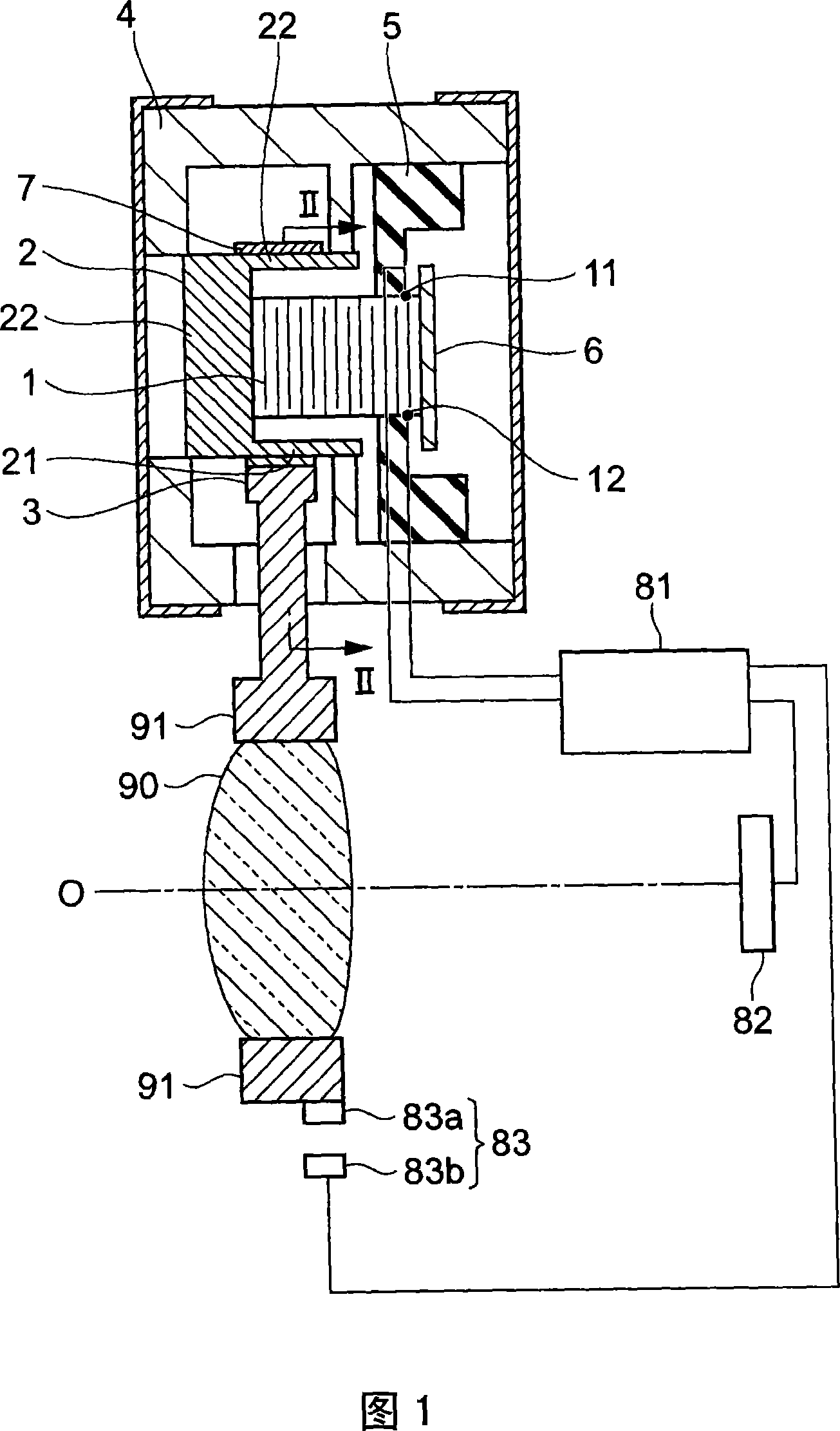
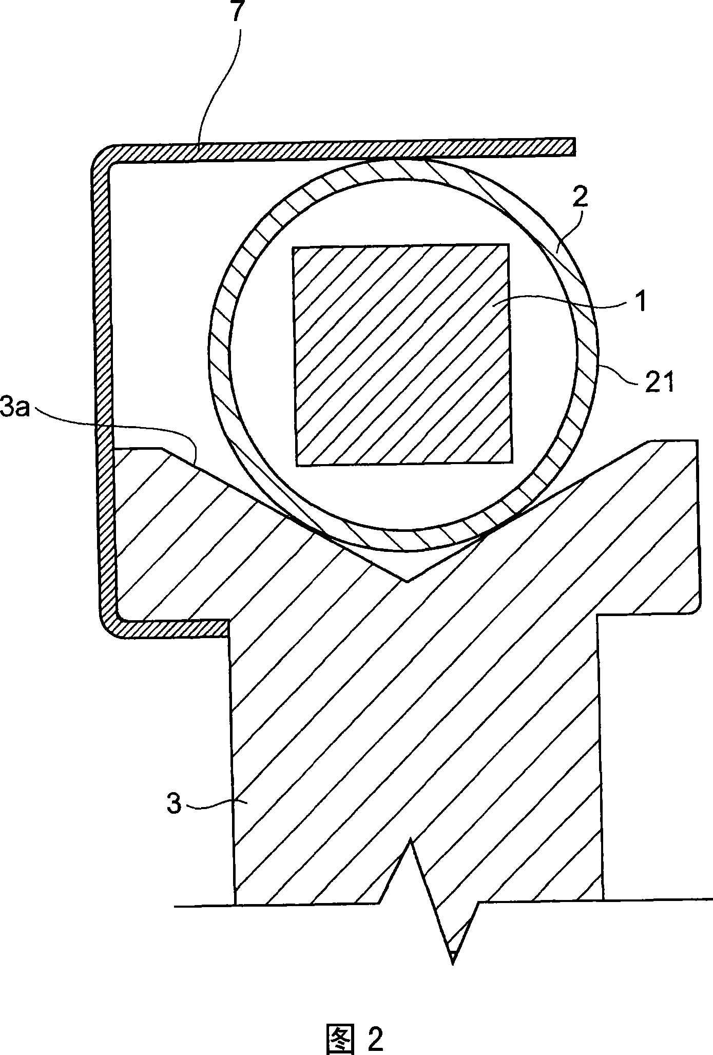
[0021] FIG. 1 is a cross-sectional view of a drive device according to an embodiment of the present invention. It is a cross-sectional view of the mounted part of the driven member in II-II of FIG. 1 .

[0022] As shown in FIG. 1 , the driving device of this embodiment moves the driving member 2 back and forth corresponding to the expansion and contraction of the piezoelectric device 1 , so that the driven member 3 frictionally engaged with the driving member 2 moves along the driving member 2 .

[0023] The piezoelectric device 1 is an electromechanical transducing device that can be expanded and contracted by the input of an electric signal, and can expand and contract in a given direction. The piezoel...


PUM


Abstract

To provide a drive unit which can downsize a device. In the drive unit which reciprocates a drive member 2, according to the expansion and contraction of a piezoelectric element 1, and shifts a driven member 3 frictionally engaged with the drive member 2, the drive member 2 has a tube 21 which is arranged to cover the piezoelectric element 1, and the driven member 3 is frictionally engaged with the tube 21. Therefore, the device can be constituted, without having such constitution that the drive member 2 elongates in the direction of expansion and contraction from the end face of the piezoelectric element 1. Accordingly, the length in expansional and contractional direction of the device can be made short, thus the device can be downsized.

Description

technical field [0001] The present invention relates to a driving device using electromechanical conversion devices such as piezoelectric devices. Background technique [0002] Conventionally, as a drive device using an electromechanical transducer such as a piezoelectric device, as described in Japanese Patent No. 2633066, there is a drive device in which a drive member (drive rod) is expanded and contracted in response to an electromechanical transducer (piezoelectric device). The reciprocating movement is performed, so that the lens barrel frictionally engaged with the driving part moves along the driving part. In the driving device, a driving component is installed on the end surface of the electromechanical converting device, and the driving component is continuously arranged on the same axis as the electromechanical converting device. [0003] [Patent Document 1] Patent No. 2633066 [0004] However, in such a drive device, the electromechanical transducer is continuo...

Claims


Application Information

Patent Timeline
Patent Type & Authority Applications(China)
IPC IPC(8): H02N2/00G02B7/04H10N30/88
CPCH02N2/025G02B7/023
Inventor 真锅充雄
Owner FUJI PHOTO OPTICAL CO LTD
Learn More