Target device for inductive displacement measurement of a master piston

A technology of target equipment and displacement measurement, which is applied in the direction of electric/magnetic position measurement, mechanical equipment, measuring devices, etc., and can solve problems such as the inability to center the aluminum target body

Active Publication Date: 2015-05-13
SCHAEFFLER TECH AG & CO KG
View PDF6 Cites 0 Cited by
  • Summary
  • Abstract
  • Description
  • Claims
  • Application Information

AI Technical Summary

Problems solved by technology

Also does not allow optimal centering of alu

Method used


Image

  • Target device for inductive displacement measurement of a master piston
  • Target device for inductive displacement measurement of a master piston
  • Target device for inductive displacement measurement of a master piston

Examples


Embodiment Construction

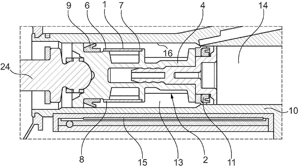
[0028] exist figure 1 shows a target device 1 which is applied to a piston body 4 . The piston body 4 is located in a master cylinder 10 with an inner wall 16 . The master cylinder 10 has a primary pressure chamber 13 and a secondary pressure chamber 14 . The piston body 4 is driven via an actuator 24 . For sealing, a first axial sealing ring 9 and a second axial sealing ring 11 are provided, the first axial sealing ring 9 sealing in the primary pressure chamber and the second axial sealing ring 11 in the secondary pressure chamber Sealing is performed in a state moving to the right according to the figure. The target device 1 is designed such that it can likewise be introduced into the secondary pressure chamber 14 . The target device 1 has a first end 6 and a second end 7 , wherein the first end 6 here forms a stop 8 for a first axial sealing ring 9 . The position of the piston body 4 or of the target device is registered via the induction coil 15 .

[0029] exist figu...


PUM


Abstract

The invention relates to a target device for inductive displacement measurement of a master piston, wherein the target device is formed as a sleeve with a slit and is produced from a metal material, and is designed for being fixed under stress on a piston body. With the target device proposed here, a master cylinder system can be constructed in a very short form and at the same time mass production can be achieved without involving additional adjustment.

Description

technical field [0001] The invention relates to a target device for inductive displacement measurement of a master piston, as well as a master piston and a hydraulic master cylinder. Background technique [0002] In the previous state of the art, solid aluminum target bodies were used which enable the inductive displacement measurement of the master cylinder. A disadvantage of such aluminum target bodies is that they are particularly space-intensive in the axial direction, since such aluminum target bodies can only be arranged above the primary pressure chamber of the master cylinder. A master cylinder with a secondary pressure chamber and a primary pressure chamber has different diameters in the two pressure chambers. An aluminum target is used to seal the gap so that it can only move in the secondary pressure chamber with a smaller diameter. In such an arrangement, the master cylinder is very long. In addition, suitable fastening devices are required in order to produce...

Claims


Application Information

Patent Timeline
IPC IPC(8): F15B15/28
CPCB60K17/02F15B15/1447F15B15/2815F15B15/2892F16D25/088F16D2025/081F16D2300/18G01B7/003G01B7/02F16D25/08
Inventor 约亨·布洛胡特
Owner SCHAEFFLER TECH AG & CO KG
Why Eureka
Try Eureka