Bonding method and bonding structure of surface acoustic wave filter

A surface acoustic filter and bonding structure technology, applied in the direction of electrical components, impedance networks, etc., can solve problems affecting device quality, internal dissipation of light, and out-of-focus abnormalities, so as to reduce the risk of out-of-focus, ensure uniformity, The effect of improving uniformity

Pending Publication Date: 2021-02-09
XIAMEN SANAN INTEGRATED CIRCUIT
View PDF8 Cites 0 Cited by
  • Summary
  • Abstract
  • Description
  • Claims
  • Application Information

AI Technical Summary

Problems solved by technology

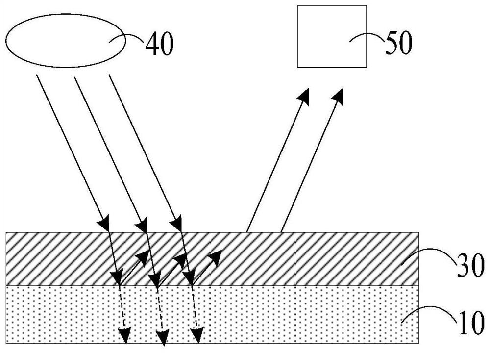
However, since the material of the bonding substrate of the surface acoustic filter is mainly a transparent material, the light will pass through the bonding substrate and be internally dissipated, which may lead to insufficient reflection signals detected by the exposure machine and cause failure. Abnormal focus, which will cause part of the photoresist to fall off and form a pattern loss, which will affect the quality of the device

Method used


Image

  • Bonding method and bonding structure of surface acoustic wave filter
  • Bonding method and bonding structure of surface acoustic wave filter
  • Bonding method and bonding structure of surface acoustic wave filter

Examples


Embodiment Construction

[0027] In order to make the purposes, technical solutions and advantages of the embodiments of the present invention clearer, the technical solutions in the embodiments of the present invention will be clearly and completely described below with reference to the accompanying drawings in the embodiments of the present invention. Obviously, the described embodiments These are some embodiments of the present invention, but not all embodiments. The components of the embodiments of the invention generally described and illustrated in the drawings herein may be arranged and designed in a variety of different configurations.

[0028] Thus, the following detailed description of the embodiments of the invention provided in the accompanying drawings is not intended to limit the scope of the invention as claimed, but is merely representative of selected embodiments of the invention. Based on the embodiments of the present invention, all other embodiments obtained by those of ordinary ski...


PUM

PropertyMeasurementUnit
thicknessaaaaaaaaaa
thicknessaaaaaaaaaa
thicknessaaaaaaaaaa

Abstract

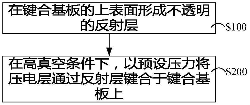
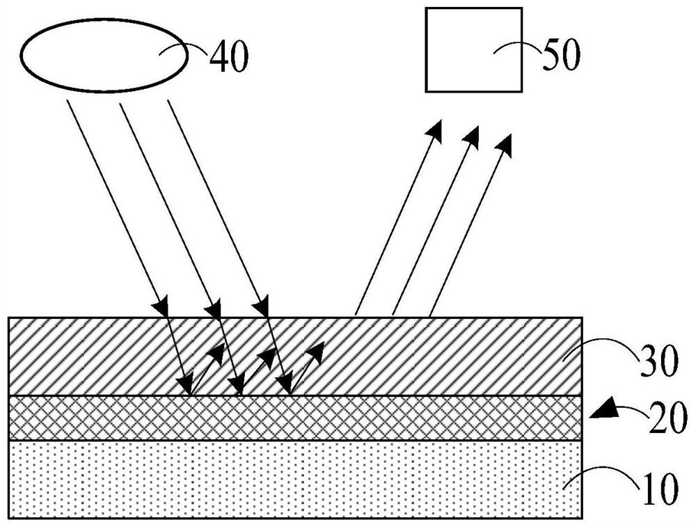
The invention discloses a bonding method and a bonding structure of a surface acoustic wave filter, and relates to the technical field of semiconductors. The bonding method of the surface acoustic wave filter comprises the following steps: forming an opaque reflecting layer on the upper surface of a bonding substrate; and under a high vacuum condition, bonding the piezoelectric layer on the bonding substrate through the reflecting layer at a preset pressure. The bonding method of the surface acoustic wave filter can effectively reduce the risk of defocusing.

Description

technical field [0001] The present invention relates to the technical field of semiconductors, and in particular, to a bonding method of a surface acoustic filter and a bonding structure thereof. Background technique [0002] The surface acoustic filter is a device composed of a pair of interdigitated electrodes formed at each end by evaporating a layer of metal film on a material substrate with piezoelectric effect, and then photolithography. When a signal voltage is applied to the transmitting transducer, an electric field is formed between the input interdigital electrodes to cause the piezoelectric material to generate mechanical vibration (ie, ultrasonic waves) to propagate to the left and right sides in the form of ultrasonic waves, and the energy to the edge side is given by Absorbed by sound-absorbing materials. At the receiving end, the mechanical vibration is converted into an electrical signal by the receiving transducer, which is output by the interdigital elect...

Claims


Application Information

Patent Timeline
Patent Type & Authority Applications(China)
IPC IPC(8): H03H3/08H03H9/02H03H9/145H03H9/64
CPCH03H3/08H03H9/02543H03H9/02622H03H9/02637H03H9/02842H03H9/02968H03H9/145H03H9/64
Inventor 罗捷林科闯谢祥政
Owner XIAMEN SANAN INTEGRATED CIRCUIT
Why Eureka
Try Eureka