
Method for producing tools especially arilling bit or milling cutter

A technology of drill bits and milling cutters, which is applied in the field of manufacturing tools and can solve problems such as drill bit manufacturing costs

Inactive Publication Date: 2008-09-24
HAWERA PROBST
View PDF8 Cites 0 Cited by
  • Summary
  • Abstract
  • Description
  • Claims
  • Application Information

AI Technical Summary

Problems solved by technology

[0003] Drills of this type are complex to produce, since first a blank with a diameter suitable for the subsequent conveying screw must be produced.

Method used


Image

  • Method for producing tools especially arilling bit or milling cutter
  • Method for producing tools especially arilling bit or milling cutter
  • Method for producing tools especially arilling bit or milling cutter

Examples


Embodiment Construction

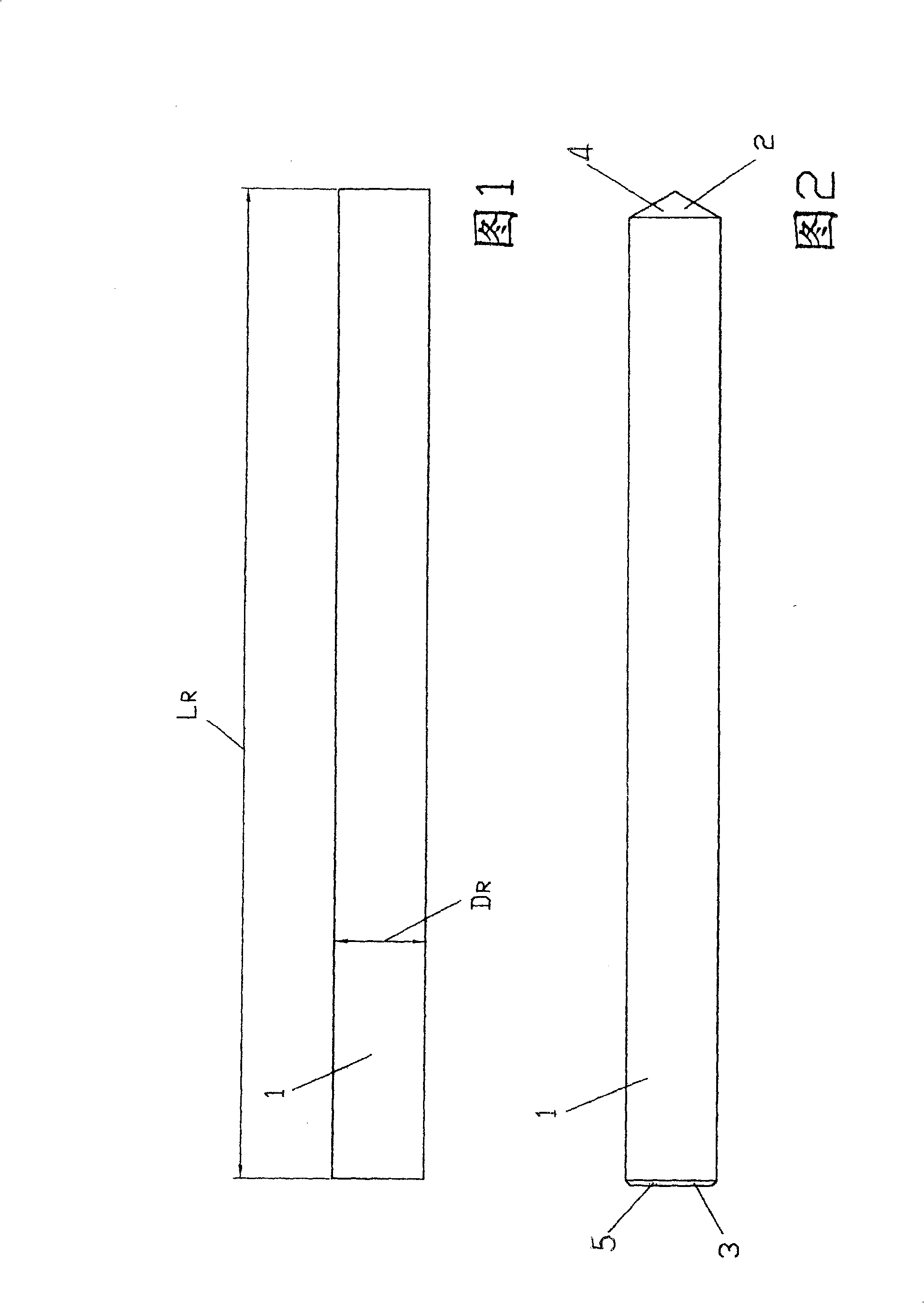
[0043] FIG. 1 shows a side view of a cut blank 1 . The blank along the length L R have a consistent diameter D R .

[0044] FIG. 2 shows the blank shown in FIG. 1 which has been machined at its end, ie has been machined to form the tip 2 and the opposite end 3 . The tip 2 is configured as a cone 4 and the end 3 is provided with a chamfer 5 .

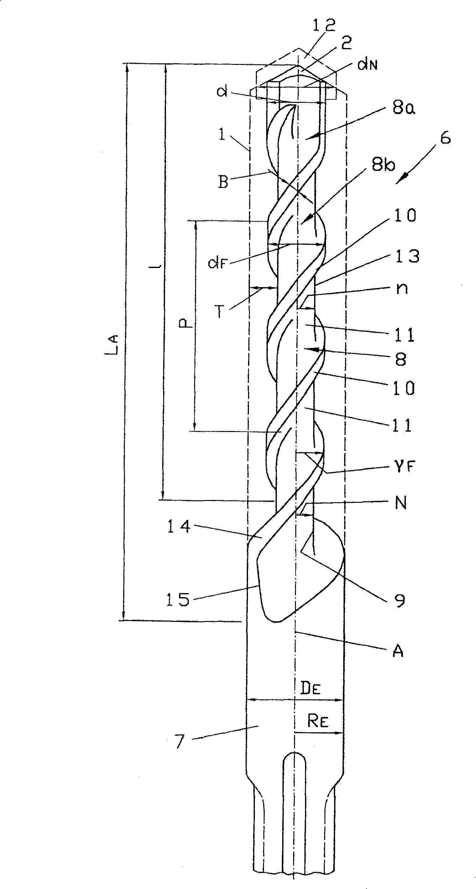
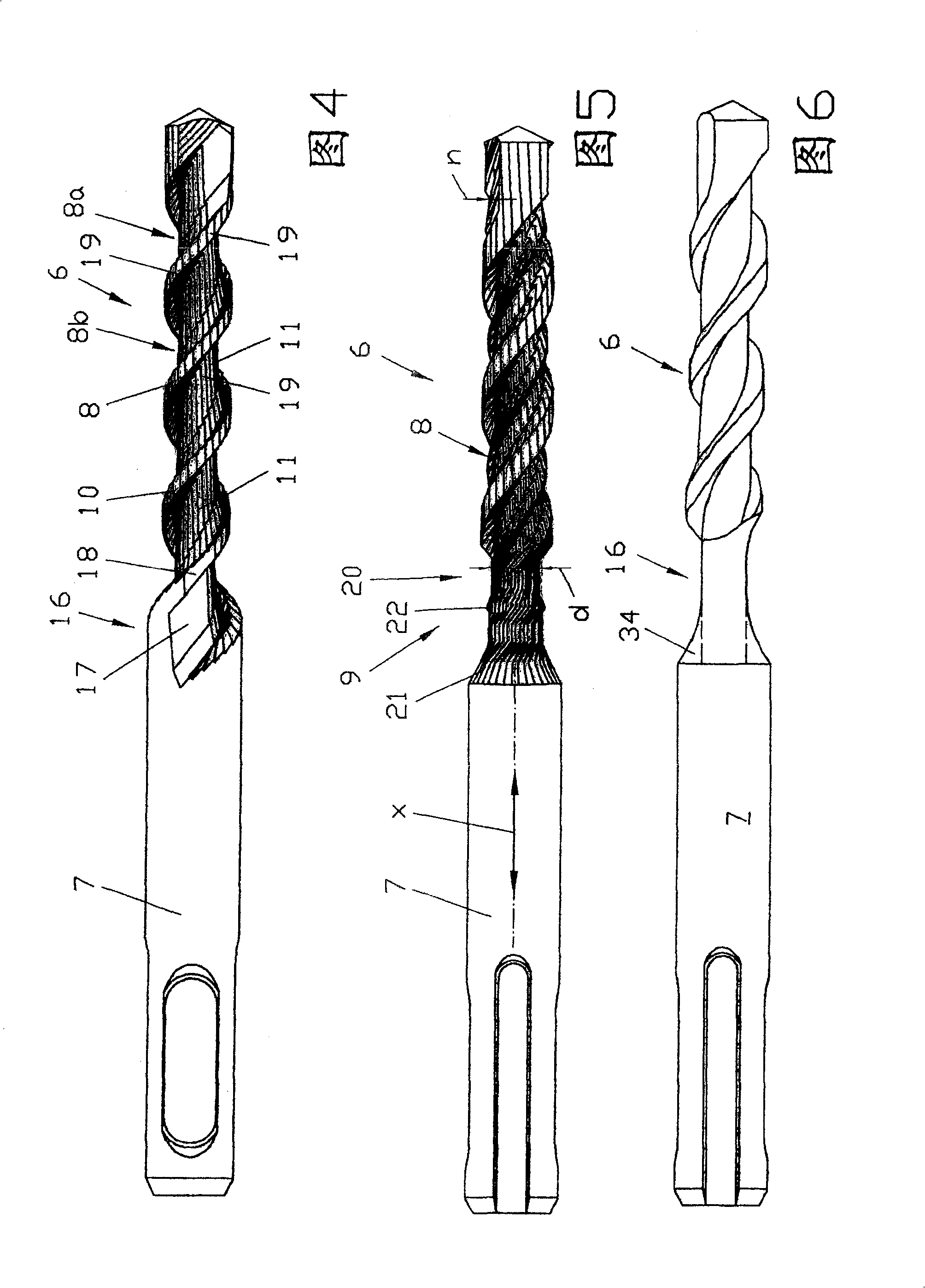
[0045] image 3 A first variant of a drill bit 6 is shown, which is produced from a blank 1 by the method according to the invention. The drill bit 6 includes a clamping shank 7 which is only partially shown with its part facing the helical part 8 . The clamping part, only partially shown, located opposite the screw part 8 is designed as an SDS-PLUS handle 33 (DE3716915A1). Alternatively, other standard shank configurations, such as SDS-MAX shank (DE2551125C2), can also be provided, or the original cross-section can be kept unchanged, such as cylindrical for fixing in the chuck.

[0046] The screw part 8 includes a screw outlet 9 ....


PUM


Abstract

The invention relates to a method for the production of a tool, in particular a drill (6) or milling cutter, having at least one conveying helix (8a, 8b), proceeding from a bar-shaped blank (1). In this case, there is provision for introducing the conveying helix (8a, 8b) in a single operation by means of a machine tool, the blank (1) having a diameter (DR) which is larger than a diameter (dF) of the conveying helix (8a, 8b).

Description

technical field [0001] The invention relates to a method for producing a tool, in particular a drill or milling cutter. Background technique [0002] The percussion drill (Hammerbohrer) is usually made of a prefabricated blank, which has a standard clamping shank (SDS-plus clamping shank) with a diameter of, for example, 10 mm, to which a cylindrical cylinder of the nominal diameter suitable for the drill to be manufactured is connected. The shank part is used later for the conveying screw. If the diameter of the conveying spiral of the drill is smaller than the diameter of the clamping shank, the blank correspondingly has a step between the clamping shank and the section provided for the conveying spiral. The blank is produced, for example, as an extruded part or as a turning blank for a so-called automatic bar machining machine. In a further working step, the conveying screw is produced in the corresponding part of the blank, for example by means of a cutting method such...

Claims


Application Information

Patent Timeline
Patent Type & Authority Patents(China)
IPC IPC(8): B23P15/32B23P15/34B23Q7/00B23P15/28B21C23/14B21K5/04B23B51/02B23C3/32B23P9/02E21B10/44
CPCB23B2251/241B23B2251/245B23C3/32B23B2251/248B21C23/147E21B10/445B23B51/02B23B2251/404B23B2226/75B21K5/04B23B2251/406B25D2217/0034B23B2251/402B23P15/32Y10T29/49996Y10T29/49995Y10T407/1948
Inventor 伯恩哈德·莫泽赖纳·维德曼汉斯-彼得·菲斯尔马尔科·朗
Owner HAWERA PROBST
Learn More