Color interpolation complement method for bel filter chip array image

A filter and color technology, applied in the field of Bell array interpolation method, can solve problems such as increasing cost and achieve the effect of reducing complexity

Inactive Publication Date: 2007-10-03
ITE TECH INC
View PDF6 Cites 1 Cited by
  • Summary
  • Abstract
  • Description
  • Claims
  • Application Information

AI Technical Summary

Problems solved by technology

Endo et al. in U.S. Patent No. US 6,853,748 and Acharya in U.S. Patent No. 6,917,381 teach multiplication and d

Method used


Image

  • Color interpolation complement method for bel filter chip array image
  • Color interpolation complement method for bel filter chip array image
  • Color interpolation complement method for bel filter chip array image

Examples


Embodiment 1

[0076] 6A and 6B are flowcharts showing a preferred embodiment of the Bell array interpolation method of the present invention. As shown in step S200, a Bell-like image is input, and a starting coordinate of the center pixel of the 3×3 pixel area is set as y=1 in step S202 and x=1 in step S204.

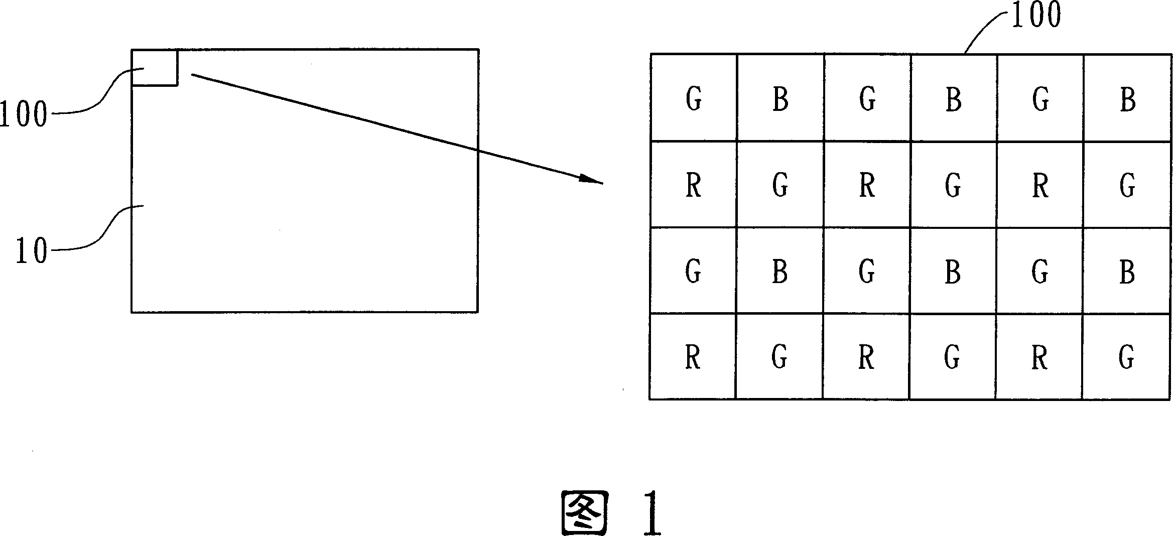
[0077] FIG. 7 is a schematic diagram illustrating a Bell image and the sequence of the color interpolation. As shown in FIG. 7 , the size of the Bell image 700 is width times height. FIG. 7 further shows a 3×3 pixel region 710 and its central pixel 711 in grayscale. The order of the color interpolation values ​​is the laser direction shown by the arrow.

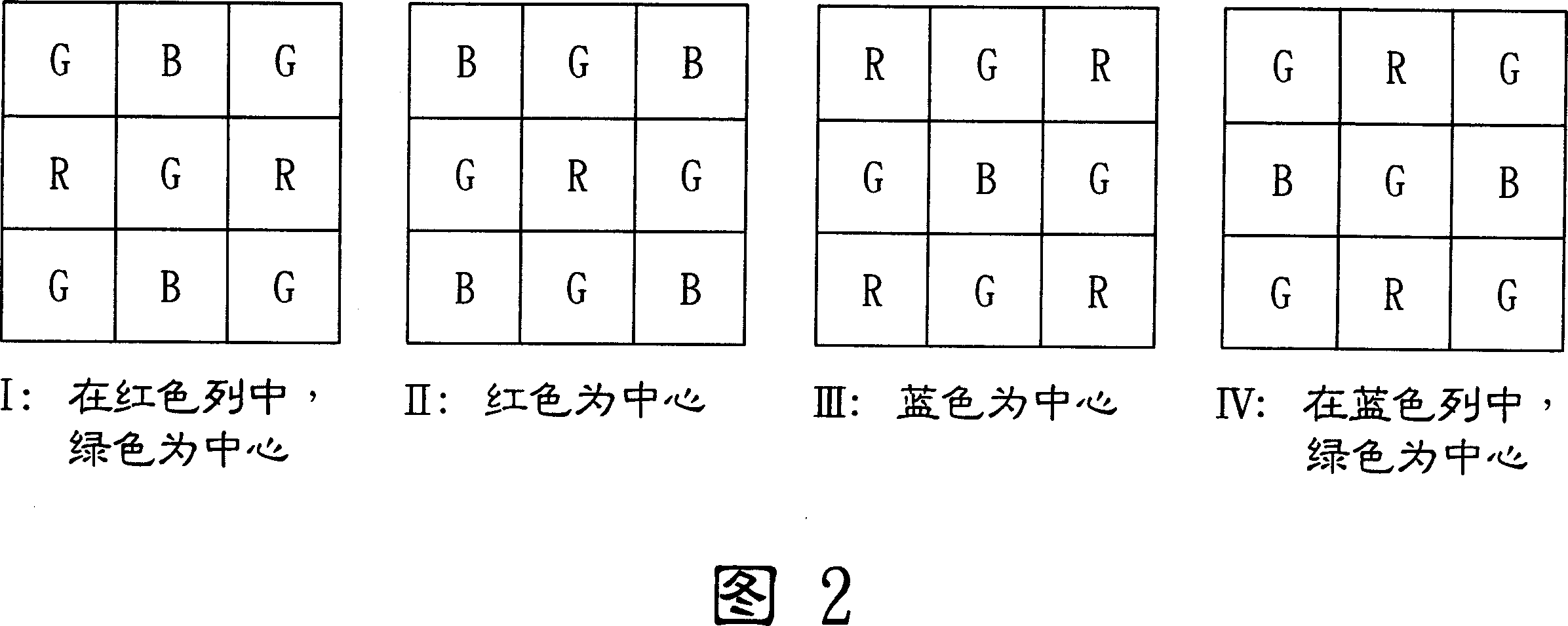
[0078] In step S206, an example of the Bell interpolation value is determined based on the contents shown in FIG. 2 .

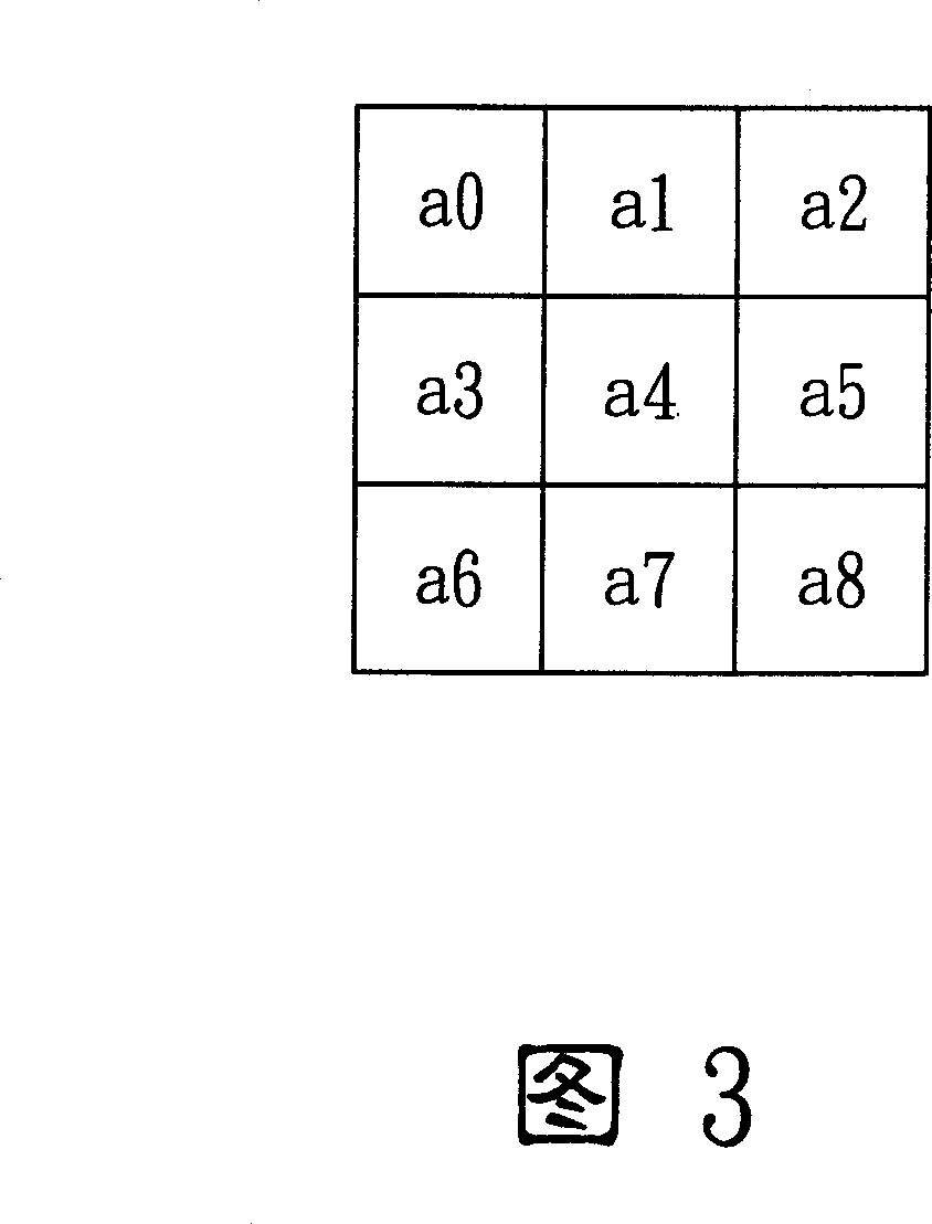
[0079] In step S208 , a green pixel difference value, a horizontal pixel difference value and a vertical pixel difference value are calculated by referring to the 3×3 pixel region in FIG. 3 . The horizontal pixe...


PUM


Abstract

This invention discloses a color complementary interpolation method used in bel filter array images, which first of all inputs a 3x3 bel sample state region with a central pixel, then decides an example of complementary interpolation of a color filter according to the kind of the central pixel to get the mean and different values of the bel pixel at level and vertical directions then to complement the missed color elements to decide a pixel activity of the 3x3 bel pixel region, finally, when the activity is high, color elements having been complemented are selected in the low difference direction.

Description

technical field [0001] The invention relates to a color interpolation method, in particular to a Bayer array interpolation method. The invention can be applied to an image processing device and an image processing method. Background technique [0002] The human visual system has three types of cones: the long cone, the medium cone, and the short cone. The cones of vision can sense wavelengths corresponding to red, green and blue light, respectively. The visual cortex in the human brain can get signals from these three types of cones, and then perform interpolation to form a shaped image. The importance of the biological architecture of the human visual system lies in the dramatic conversion of the vast, entire visible spectrum to be processed into only the primary colors red, blue and green. [0003] Therefore, the digital image sensor in a digital camera is also designed to be similar to the cone of vision of the human visual system. One of the most commonly used image ...

Claims


Application Information

Patent Timeline
IPC IPC(8): H04N9/04
Inventor 林文国
Owner ITE TECH INC
Why Eureka
Try Eureka