
Electrode and enclosure for cardiac monitoring and treatment

An electrode and shell technology, applied in the field of medical electrodes and shells, can solve problems such as damage, non-conductive base layer environmental pollution, perforation, etc.

Active Publication Date: 2007-10-10
KONINKLIJKE PHILIPS ELECTRONICS NV
View PDF1 Cites 8 Cited by
  • Summary
  • Abstract
  • Description
  • Claims
  • Application Information

AI Technical Summary

Problems solved by technology

First, the operator must open the sealed bag
Second, the operator must plug the electrode connector into the AED base unit
Third, the operator must remove the release liner from one electrode, which usually covers the gel on the electrode pad, and fourth, the operator must place the electrode on the patient
However, storing the package in this form is undesirable as the exposed backside of the non-conductive base layer may be subject to environmental contamination or be perforated or damaged

Method used


Image

  • Electrode and enclosure for cardiac monitoring and treatment
  • Electrode and enclosure for cardiac monitoring and treatment
  • Electrode and enclosure for cardiac monitoring and treatment

Examples


Embodiment Construction

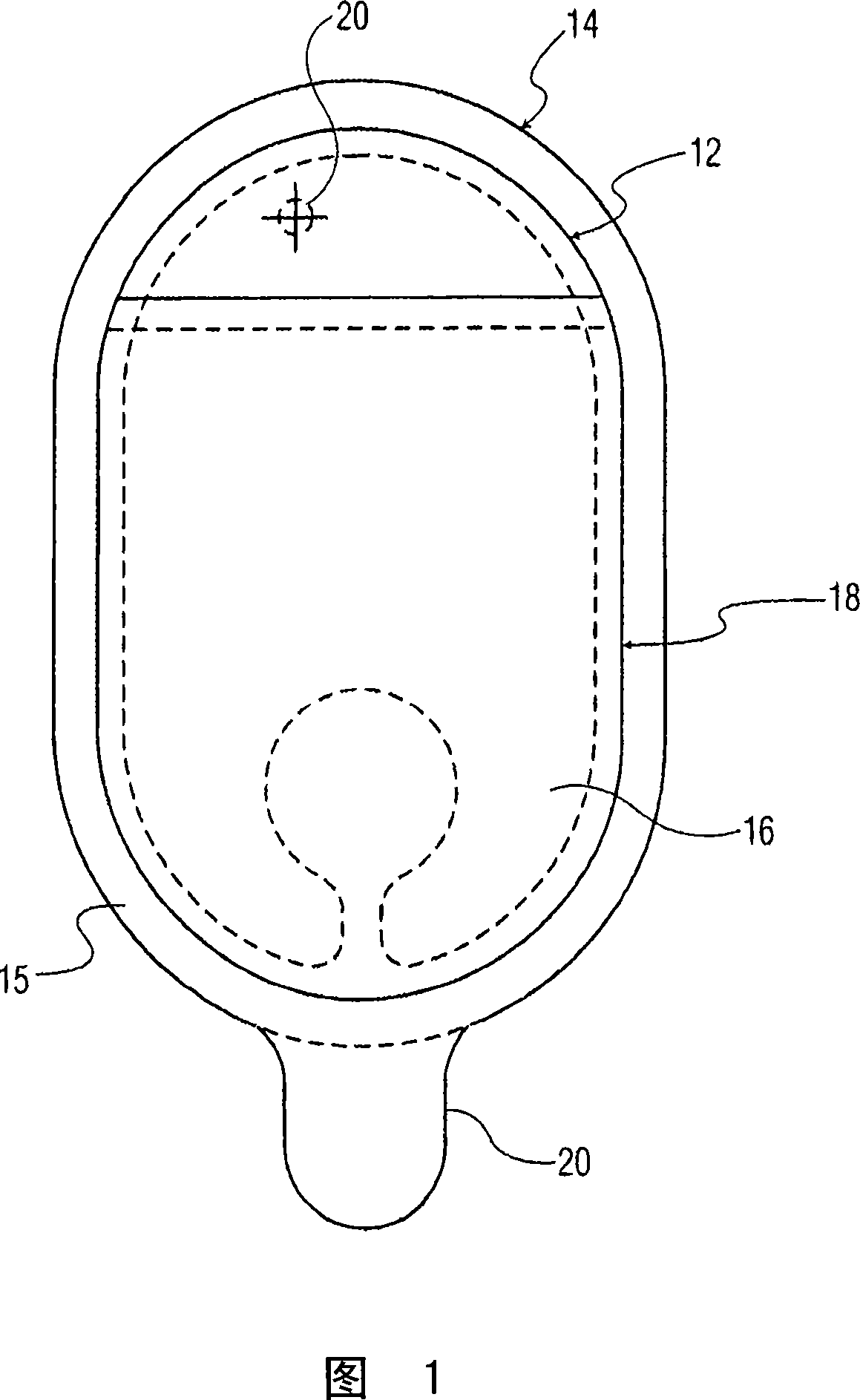
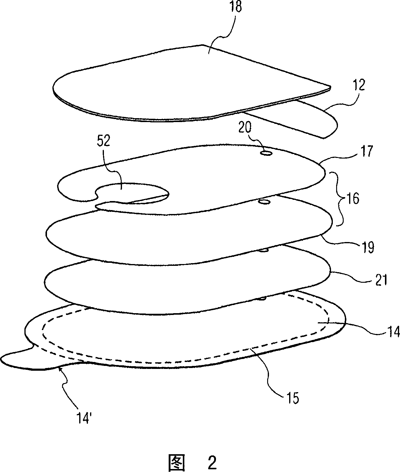
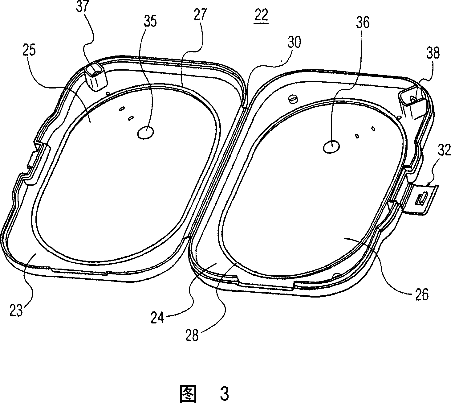
[0021] Referring now to the drawings, in which like numerals indicate like parts, FIG. 1 illustrates a top view of a medical electrode 10 constructed in accordance with the principles of the present invention. Medical electrode 10 includes an electrode body having first and second sides, wherein the first side includes a flexible barrier layer 14 including a heat seal material disposed around at least a perimeter 15 thereof, and the second side includes a conductive layer 16 . The medical electrode 10 also includes a conductive gel layer 18 disposed on the electrode body 10 and electrically connected to the conductive layer 16 . Holes 20 for rivets allow the connection of electrode wires (not shown in this view) to the electrodes 10 . The rivet cover 12 covers the rivet hole so as to prevent direct electrical connection between the patient and the electrode wire connector when the electrode 10 is adhered to the patient. Rivet cover 12 also overlies a portion of conductive lay...


PUM


Abstract

A defibrillator electrode (10) and enclosure (23, 24) are described in which the electrodes are sealed to the inside of a rigid enclosure (23, 24). The enclosure is hinged to open and expose the electrodes for deployment. The electrode gel is sealed against moisture loss between the moisture impervious electrode backing and the inner surface of the enclosure. The enclosure may further include an electrical circuit for electrode self-testing, the circuit being broken when the enclosure is opened.

Description

technical field [0001] The present invention relates generally to electrodes for medical devices, and in particular to medical electrodes and housings for cardiac monitors or defibrillation / pacing devices. Background technique [0002] Sudden cardiac death is the leading cause of death in the United States. Most sudden cardiac deaths are caused by ventricular fibrillation ("VF"), in which the heart muscle fibers contract uncoordinated, thereby interrupting normal blood flow to the body. The only known treatment for VF is electrical defibrillation, in which electrical impulses are applied to the patient's heart. This shock clears the heart of abnormal electrical activity (in a process called "defibrillation") by depolarizing a critical mass of cardiomyocytes to allow spontaneous tissue resuscitation from myocardial depolarization. [0003] One method of providing electrical defibrillation is an automatic or semi-automatic external defibrillator, collectively referred to as ...

Claims


Application Information

Patent Timeline
IPC IPC(8): A61N1/04A61B5/276
CPCA61N1/0472A61N1/046A61B5/0424A61N1/048A61N1/0492A61B2562/125A61B5/276A61B5/282
Inventor D·J·鲍威尔斯S·冯E·约恩森P·豪格
Owner KONINKLIJKE PHILIPS ELECTRONICS NV
Learn More