Optical integrator, illuminator and projection image display

An optical integrator and lighting device technology, applied in optics, projection devices, optical components, etc., can solve the problems of large-scale weight of the device, increased working sound of the device, large-scale device, etc., and achieve miniaturization and low cost , Prevent the widening of the optical path width and improve the utilization efficiency

Inactive Publication Date: 2007-10-10
SHARP KK
View PDF5 Cites 24 Cited by
  • Summary
  • Abstract
  • Description
  • Claims
  • Application Information

AI Technical Summary

Problems solved by technology

[0033] First of all, since the wavelength region of the emitted light from the lamp includes ultraviolet rays to infrared rays, there is a problem of thermal influence on the light valve (DMD, liquid crystal panel) and other components.
In addition, in order to avoid the influence of heat, if a cooling fan is installed inside the device, it is necessary to install an ultraviolet and infrared cut-off filter on the output part of the lamp, which increases the cost of the device, and generates high noise caused by the fan during the operation of the device, so there are related problems. Problems of device size and weight increase
In addition, in the case of the lamp method, after 2,000 hours to 4,000 hours of lighting, when the life of the lamp is reached, the image displayed on the screen becomes dark, and the expensive lamp must be replaced.
[0034] In addition, in the device of the DLP method as shown in Figure 10, in order to carry out the operation sound of the motor and the wind sound caused by the rotation of the color wheel, and because the above-mentioned cooling fan is installed to generate the operation sound of the fan motor and the wind sound of the fan, there is a noise in the whole device. The problem of increased working sound
[0035] In addition, in the LCD device shown in Figures 11 and 12, the lamp is a white light source, so for the color separation of the outgoing light, a dichroic mirror must be installed, and because the outgoing light of the lamp has a widening angle, it must be arranged in the optical path The large-sized dichroic mirror on the downstream side has the problem of increasing the overall size of the device
[0036] In addition, in the projection type image display device 20 using the cross prism 28 shown in FIG. There is a problem that the liquid crystal panels 27R, 27G, and 27B must be arranged with strict positional accuracy with respect to the incident surface of the cross prism 28.
As shown in Figure 14, when the cross prism 43 is used, generally because the price of the cross prism itself is high, it is difficult to reduce the cost of the projection type image display device, and it is also because the widening angle of the outgoing light of each LED 41R, 41G, 41B is taken into account. , it is also often necessary to use large and heavy cross prisms43
[0038] Also, as a problem common to both the types shown in FIGS. 13 and 14, when the shapes of the LEDs 31R, 41R, etc. are different from the aperture shapes of the liquid crystal panels 37, 47, from the viewpoint of imaging magnification, it is impossible to effectively use the LEDs 31R, 41R, etc. 41R etc. all outgoing light
In addition, in order to obtain high screen illuminance, high-output high-power LEDs must be used as light sources. The problem at this time is that in order to take measures against the heat dissipation of high-power LEDs, dichroic mirrors 33R, 33G, etc. or cross prisms cannot be used. 43 are arranged on one plane, which leads to a larger size of the device due to the complexity of the heat dissipation structure

Method used


Image

  • Optical integrator, illuminator and projection image display
  • Optical integrator, illuminator and projection image display
  • Optical integrator, illuminator and projection image display

Examples


Embodiment Construction

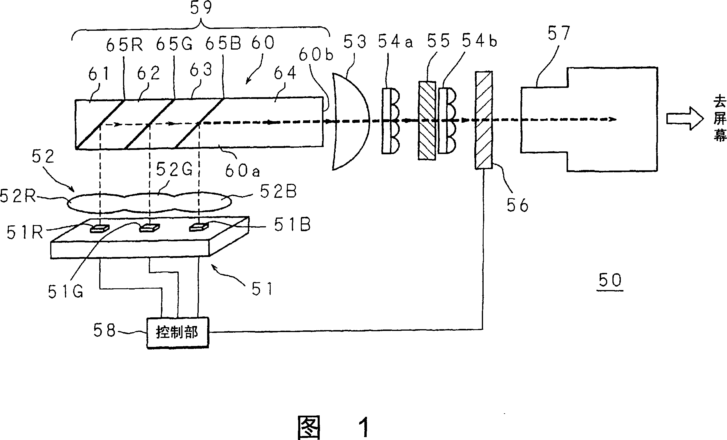
[0107] 1 shows the configuration of a projection-type image display device 50 (including an illuminating device 59 ) according to the first embodiment of the present invention. The projection-type image display device 50 according to the first embodiment is a form in which most of the contents of the present invention are collectively configured. Suitable for cost reduction and miniaturization.

[0108]The projection type image display device 50 uses a plurality of light-emitting elements, that is, the red LED 51R, the green LED 51G, and the blue LED 51B as light sources. Outgoing light from the first lens 52 is incident. In the projection-type image display device 50, the second lens 53, the first fly-eye lens 54a, and the PS separation / combination unit 55 are respectively disposed on the downstream side from the output surface 60b serving as the end (end face) in the longitudinal direction of the optical integrator 60. The second fly-eye lens 54b, the transmissive liquid cr...


PUM


Abstract

Size and cost of an apparatus are reduced by reducing the optical path length of light emitted from a light source while enhancing utilization efficiency of the light source. A projection image display (50) employs LEDs (51R, 51G, 51B) as the light source and directs an emitted light beam to enter an optical integrator (60). The optical integrator (60) is formed by bonding four block members (61-64) in the longitudinal direction wherein a dichroic mirror (65R) reflecting an R light beam and transmitting G and B light beams, a dichroic mirror (65G) reflecting a G light beam and transmitting R and B light beams, and a dichroic mirror (65B) reflecting a B light beam and transmitting R and G light beams are provided integrally on the inclining bonding face of each block member (61-64). Each dichroic mirror (65R, 65G, 65B) reflects the light emitted from each LED (51R, 51G, 51B) and propagates them through the optical integrator (60) while reflecting totally and outputs a uniform light beam from an exit face (60b).

Description

technical field [0001] The present invention relates to an optical integrator and an illumination device capable of efficiently utilizing a light source, and a projection-type image display device that realizes high-quality image display in view of miniaturization. technical background [0002] As a front projection method, there is a projector (projection type image display device) that projects modulated light related to an image generated by a light source on a screen and displays an image on the screen. The configuration of such a projection-type image display device is also applicable to a rear projection method represented by a rear projection television. When a projection type image display device uses a lamp as a light source, light-emitting elements such as lasers and diodes are used. On the other hand, when it is classified by the type of spatial light modulation element (light valve) that generates the original image of the projection object, it is divided into D...

Claims


Application Information

Patent Timeline
Patent Type & Authority Applications(China)
IPC IPC(8): G03B21/00G03B21/14
CPCH04N9/3197G02B27/1053G02B27/145G02B27/149G03B21/14H04N9/3111H04N9/3152G03B21/2066G03B33/12G03B21/00G02B27/00
Inventor 京本忠男岩内谦一
Owner SHARP KK
Why Eureka
Try Eureka