
Embedded type connector for printed circuit board

A printed circuit board, embedded technology, applied in the direction of conductive connection, circuit, connection, etc., can solve problems such as complex production

Inactive Publication Date: 2007-10-10
ADC GMBH
View PDF3 Cites 4 Cited by
  • Summary
  • Abstract
  • Description
  • Claims
  • Application Information

AI Technical Summary

Problems solved by technology

A disadvantage of known embedded connectors for printed circuit boards is that their production is relatively complicated

Method used


Image

  • Embedded type connector for printed circuit board
  • Embedded type connector for printed circuit board
  • Embedded type connector for printed circuit board

Examples


Embodiment Construction

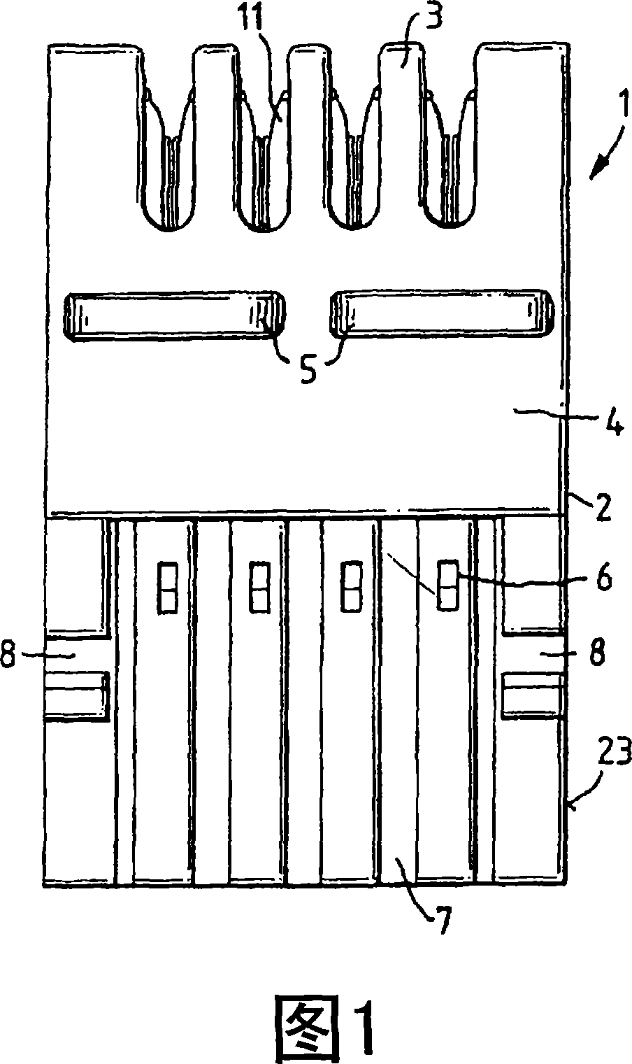
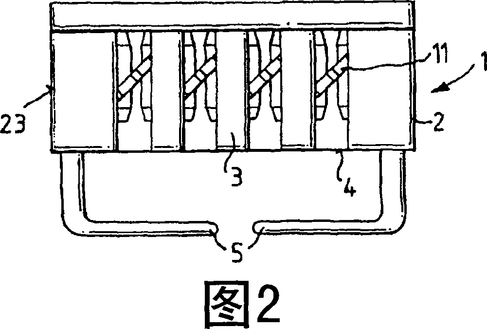
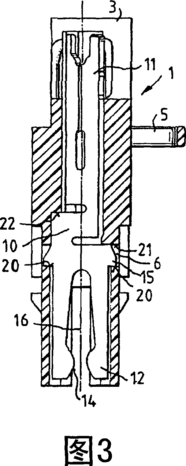
[0017] In FIG. 1, the embedded connector 1 is shown in a side view. The embedded connector 1 includes an integral plastic shell 2 . In the upper region, the plastic housing 2 is formed with clamping ribs 3 between which the insulation piercing contacts 11 of the contact part 10 are arranged (shown in FIG. 4 ). The wire guide 5 is arranged below the clamping rib 3 on the housing wall. The forked contacts 12 of the contact part 10 are arranged in the lower region of the plastic housing 2 , which has a snap-in receptacle 6 formed as a rectangular hole. Between the respective pair of detent sockets 6 , the housing wall 4 has a groove-shaped depression 7 . Furthermore, the housing wall 4 has two sockets 8 on both sides for a locking mechanism (not shown), through which the snap-in connector 1 can be fastened, for example, to a metal front frame. The housing wall 4 is formed on the inside with a slot 9 in which the forked contacts 12 are guided with their side surfaces 13, in whi...


PUM


Abstract

The invention relates to a plug-in connector for printed circuit boards, comprising a plurality of contact elements, whereby said contact elements have two connecting faces each. The one connecting face is configured as an insulation displacement contact for connecting cores and the other connecting face is configured as a tuning fork contact for contacting contact surfaces on a printed circuit board. The insulation displacement contacts of the contact elements can be inserted into a plastic housing. The insulation displacement contact and the tuning fork contact are arranged in a rotational manner in relation to each other and the contact element is supported on the plastic housing by at least one edge, such that the contact elements are captivated in the plastic housing when connecting forces act upon the insulation displacement contacts. The plastic housing is embodied as a single piece and the part receiving the tuning fork contact is at least partially elastic.

Description

technical field [0001] The invention relates to a built-in connector according to the preamble of claim 1 . Background technique [0002] DE19945412A1 and DE10257308B3 respectively disclose an embedded connector for printed circuit boards, including: a plurality of contact parts, the contact parts respectively have two connection surfaces, and one connection surface is formed as an insulation piercing contact for connecting wires (insulation-piercing contact), while the other connection surface is configured as a bifurcated contact (bifurcated contact) for contacting the terminal area on the printed circuit board; and a plastic housing, in which the insulation piercing contact and the bifurcated contact Arranged so that they rotate relative to each other and at least one lower edge of the insulation piercing contact is supported on the plastic housing such that when a connecting force occurs on the insulation piercing contact the contact part is captured and held within the ...

Claims


Application Information

Patent Timeline
Patent Type & Authority Applications(China)
IPC IPC(8): H01R12/32H01R4/24H01R12/18H01R12/55H01R13/422
CPCH01R4/2429H01R13/50H01R13/112H01R13/422H01R12/515H01R12/55
Inventor H·诺伊梅茨勒
Owner ADC GMBH
Learn More