Horizontal and tuning fork vibratory microgyroscope

a technology of horizontal and tuning fork, which is applied in the direction of acceleration measurement using interia force, turn-sensitive devices, instruments, etc., can solve the problems of low detection performance of conventional horizontal microgyroscope, difficult frequency tuning, and bad vibrations transmitted in the directions of x and y, so as to minimize the

Inactive Publication Date: 2005-07-19
SAMSUNG ELECTRO MECHANICS CO LTD
View PDF5 Cites 44 Cited by
  • Summary
  • Abstract
  • Description
  • Claims
  • Application Information

AI Technical Summary

Benefits of technology

[0020]It is another object of the present invention to provide a horizontal and tuning fork vibratory microgyroscope which is capable of minimizing effects due to any external vibration or noise.

Problems solved by technology

Consequently, the vibrations transmitted in the directions of X and Y may have bad effects on the results of the detection when the angular velocity is detected as mentioned above.
The conventional horizontal microgyroscope has low detection performance especially when vibrating at a rate near a natural frequency among the external vibrations.
Consequently, it is required that the height and thickness of elastic elements, such as springs, which vibrate in the horizontal and vertical directions, be identical, which makes tuning of the frequency very difficult.
Consequently, it is required to perfectly control the aforesaid processes, which is practically difficult.
As described above, the conventional horizontal or tuning fork microgyroscope has problems in that vibration is transmitted to the structure of the microgyroscope due to external vibration or noise, and therefore other signals interference with the measurement of the angular velocity is considerably increased.
In practical applications, occurrence of such interfering signals due to vibration or noise may have bad effects upon the performance of the microgyroscope.

Method used


Image

  • Horizontal and tuning fork vibratory microgyroscope
  • Horizontal and tuning fork vibratory microgyroscope
  • Horizontal and tuning fork vibratory microgyroscope

Examples


Embodiment Construction

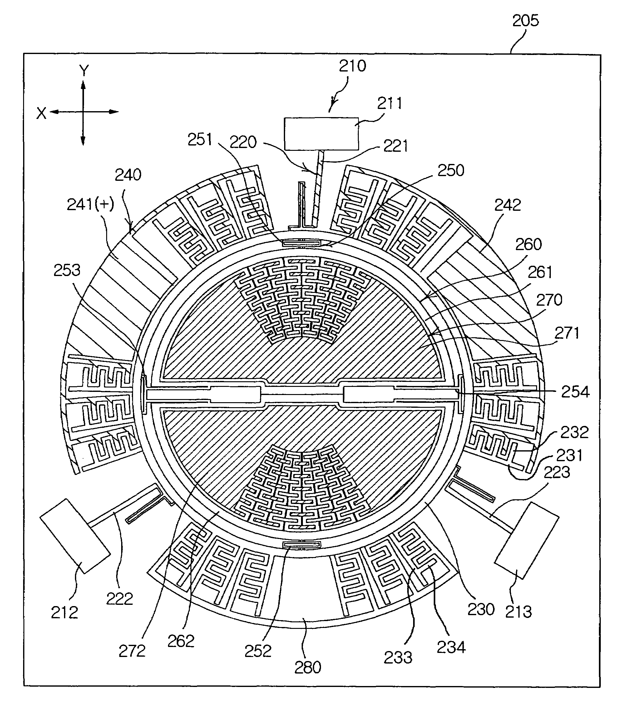
[0037]The present invention uses a tuning fork mode in which a pair of weighted elements are opposite to each other in such a manner that the weighted elements are alternately close to or away from each other. A strong point of the tuning fork mode is that since the weighted elements move facing each other, the microgyroscope is negligibly affected by external vibration. Furthermore, a rotational movement is generated even in a second resonance mode, which is used as a sensing mode. Consequently, the effect of external linear vibration is minimized. In order to use the tuning fork mode, two inner weighted elements must be accurately coupled with each other. Some of preferred embodiments for construction of such a microgyroscope will now be described.

[0038]An outer frame and a pair of inner weighted elements of the microgyroscope according to the present invention are elastically supported by an outer elastic element unit and an inner elastic element unit. The sizes of the weighted e...


PUM


Abstract

A horizontal and tuning fork vibratory microgyroscope detects angular velocity and angular acceleration of an inertial object when the inertial object is rotated, wherein resonance directions of the microgyroscope are on the same horizontal plane in both sensing and driving modes. The microgyroscope includes a substrate, an anchored pad unit, an outer elastic element unit, an outer frame, a sensing electrode unit, an inner elastic element unit including a plurality of inner elastic elements connected to the inside of the outer frame, an inner weighted element unit including a pair of first and second inner weighted elements each having a driven comb, and a driven electrode unit including a comb drive forming a comb structure.

Description

RELATED APPLICATIONS[0001]The present application is a divisional of U.S. patent application No. 10 / 610,624, filed Jul. 2, 2003, the disclosure of which is hereby incorporated by reference herein in its entirety.BACKGROUND OF THE INVENTION[0002]1. Field of the Invention[0003]The present invention relates to a horizontal and tuning fork vibratory microgyroscope for detecting angular velocity and angular acceleration of an inertial object when the inertial object is rotated, and more particularly to a horizontal and tuning fork vibratory microgyroscope in which resonance directions of the microgyroscope are on the same horizontal plane in both sensing and driving modes, whereby its sensing characteristics are highly improved irrespective of changes to its vertical thickness determined in a process for manufacturing the microgyroscope.[0004]2. Description of the Related Art[0005]As well known to those skilled in the art, a gyroscope is widely used as a sensor for detecting angular velo...

Claims


Application Information

Patent Timeline
Patent Type & Authority Patents(United States)
IPC IPC(8): G01C19/56G01C19/00G01C19/5712G01C19/5747
CPCG01C19/56G01C19/00
Inventor PARK, KYU YEON
Owner SAMSUNG ELECTRO MECHANICS CO LTD
Why Eureka
Try Eureka