Static mixer

A technology of static mixers and mixers, applied in the direction of fluid mixers, mixers, mixers with rotating containers, etc.

Active Publication Date: 2007-10-17
MEDMIX SWITZERLAND AG
View PDF5 Cites 18 Cited by
  • Summary
  • Abstract
  • Description
  • Claims
  • Application Information

AI Technical Summary

Problems solved by technology

[0003] Especially if the quantities to be mixed are very small, for example in the case of dropwise dispensing, the use of mixers with conventional mixing elements is problematic, since in particular for ingredients with different viscosities and corresponding surface tensions, different to achieve a thorough mixing effect

Method used


Image

  • Static mixer
  • Static mixer
  • Static mixer

Examples


Embodiment Construction

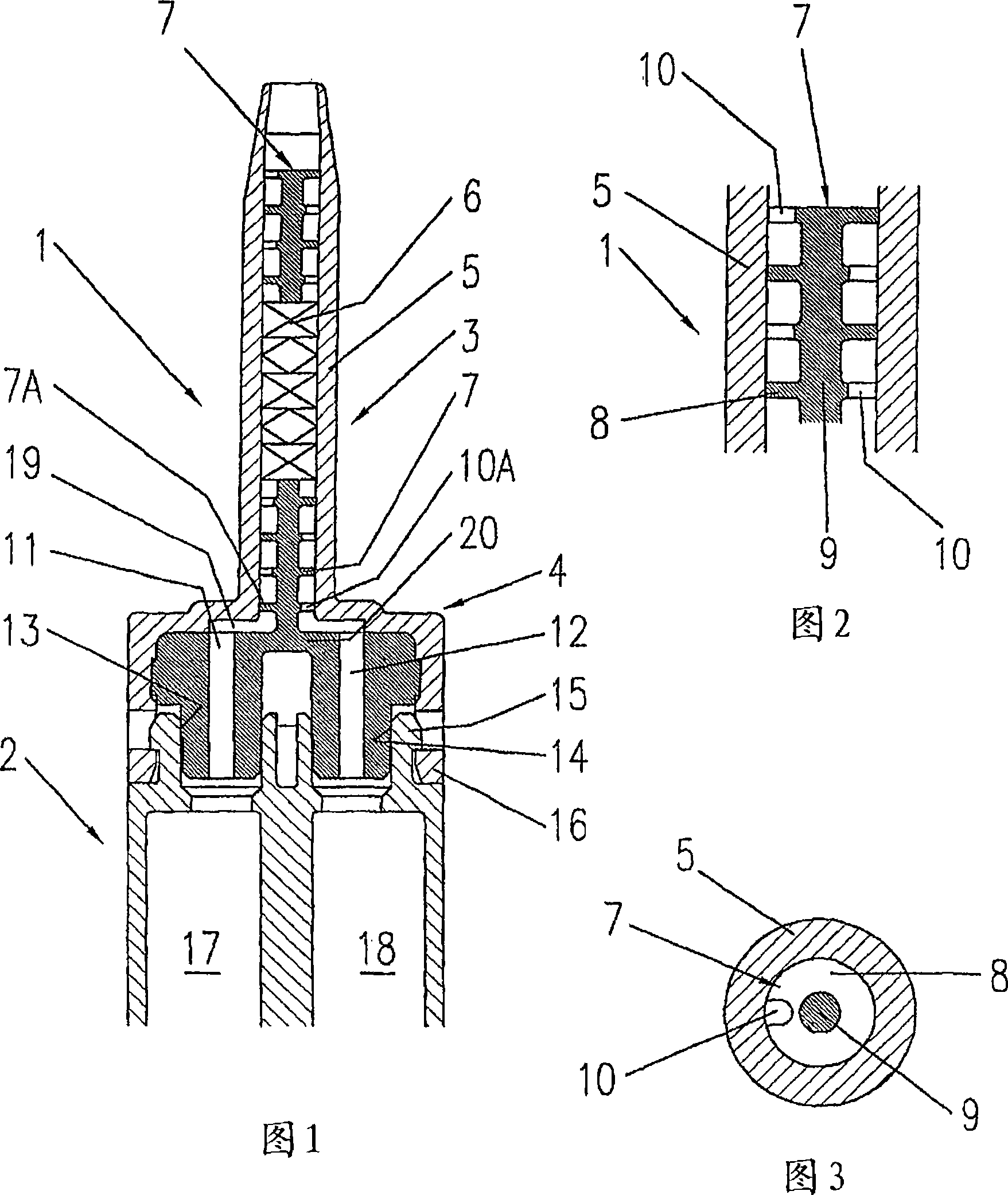
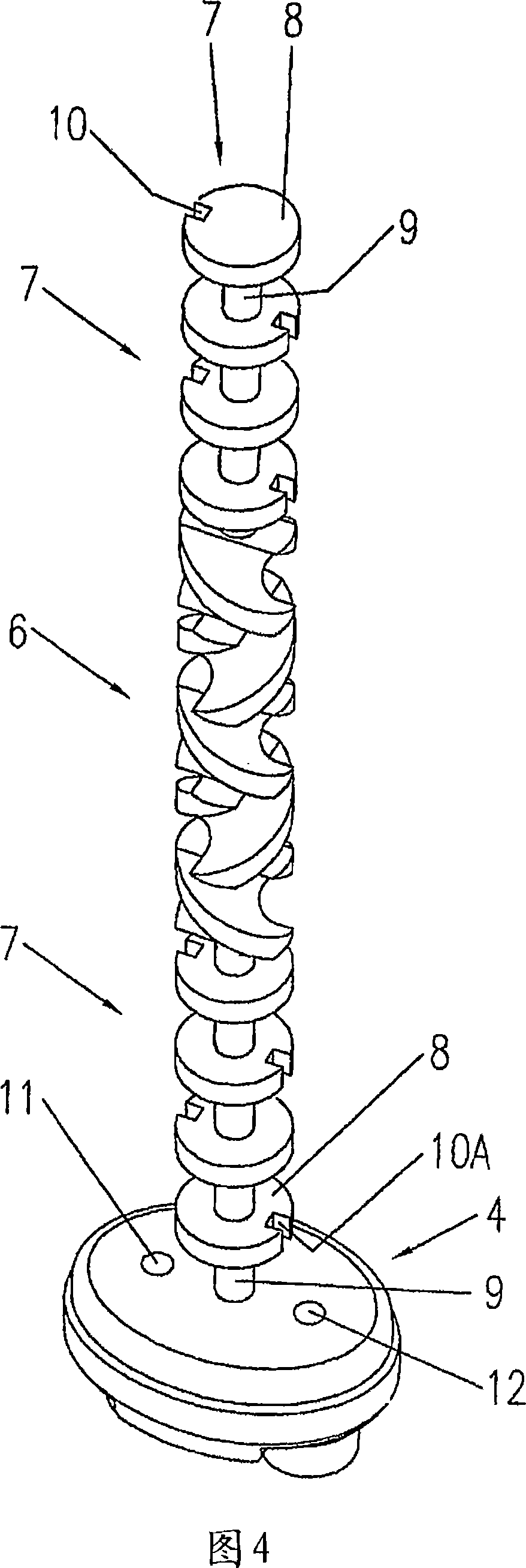
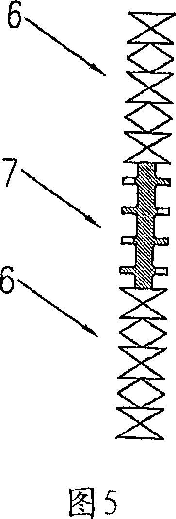
[0018] FIG. 1 shows a longitudinal section of a mixer 1 according to the invention fastened to a two-component cartridge 2 and having a housing 3 with an inlet portion 4 . Different types of mixing elements are arranged in the cylindrical housing part 5 . In the middle part of the mixing element, a conventional mixing spiral 6 is arranged, flanked by novel mixing elements 7 , see also FIGS. 2 and 3 .

[0019] The novel mixing element 7 is designed as a shear plate and comprises a disc 8 fastened to a hub 9 and having channels 10 . As shown particularly in FIG. 2 , the channels 10 are arranged such that each channel is rotationally offset, eg, by 180°, relative to an adjacent channel. The shape of the channel is chosen such that the liquid is subjected to high velocity or shear stress, respectively, so as to create subsequent eddies and ensure good mixing of even the smallest quantities. However, the specific shape is not limited to the illustrated shape and may be different ...


PUM


Abstract

The static mixer for two components comprises a housing (3) having an input part (4) and mixing elements disposed inside the housing. Known mixers use mixer helices as the mixing elements. The inventive mixer is characterized in that at least one mixing element is configured as a discoid shear blade (7, 7A) having a passage (10, 10A) on its disk (8). Such shear elements allow to mix even very small quantities, which are delivered dropwise, since higher shearing rates are produced during discharge at the shear blade passages and vortices are produced at the discharge end, which is particularly advantageous for the use of such mixers in the medical field.

Description

technical field [0001] The invention relates to a static mixer for two components according to the preamble of claim 1 , comprising an inlet part and a housing inside which mixing elements are arranged. Background technique [0002] It has been known for a long time to mix two substances by means of static mixers, most of which comprise helical mixing elements as described in US-A-5 609 271 to the applicant of the present invention. In this principle, two substances are mixed with each other by repeated movements. In order to achieve high-quality mixing, different parameters of the mixer are determined in various ways, such as the geometry of the mixing elements, the number of mixing elements and the diameter of the mixer. In static type mixers, laminar flow is usually used for media with medium to high viscosity. The same applies to mixers with a very small diameter, eg 1-2 mm, and to ingredients with low viscosity. [0003] Especially if the quantities to be mixed are v...

Claims


Application Information

Patent Timeline
Patent Type & Authority Applications(China)
IPC IPC(8): B01F5/06B01F13/00B01F29/85
CPCB01F5/0682B01F2215/0032B01F5/0688B05C17/00509B01F2215/0039B01F5/0612B05C17/00506B01F5/0615B01F5/0608B01F25/4233B01F25/4312B01F25/43141B01F25/45B01F25/4521B01F2101/22B01F2101/2305
Inventor 威廉·A·凯勒
Owner MEDMIX SWITZERLAND AG
Why Eureka
Try Eureka